diy solar

diy solar

It's like a jigsaw puzzle that could kill me (setting up my bus bar) - my thoughts make sense?

AlaskanNoob

Solar Enthusiast
Joined
Feb 20, 2021
Messages
903
Overview.jpg

Alright, maybe a 48V bus bar shouldn't kill me, but it's not out of the realm of possibility that I'd try wiring a solar string directly to it...

Anyway, I'm trying to finalize the cable lengths for the Quattro and MPPT connecting to the bus bar before I put in the order. I set my Quattro 4" from the MPPT to comply with the spacing distances (we will have an identical second MPPT but we're not installing it yet because our custom solar ground mounts broke our bank and so we're only putting in two strings this summer, hence only wiring in a single MPPT for right now).

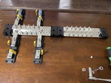
Positive bus bar with two large T-fuse holders, and two smaller T-fuse holders. The two smaller holders in the center will go to the MPPT (two positive cables going to two positive connections). The two larger holders on the outside will go to the Quattro. All 8 remaining unoccupied positive studs will go to 8 Pylontech US5000 batteries.

Three questions for the generous out there:

A) I measure my positive cable length as 18" for the two Quattro positive cables, and 19" for the two MPPT positive cables. Should I go with those numbers to keep it as short as possible, or round it up to 24" to give me some wiggle room? I could also move the bus bars closer to the devices and shorten the lengths if needed a bit.

19 inches.jpgB) How far away should my negative bus bar on the bottom be away from the positive bus bar, or does it matter? I know I want to keep it relatively close so that my negative cables won't be too much longer than their positive cable counterparts, but I'm under the impression that I don't want to make it easy to drag my keys or something across both at the same time (they have covers, so I imagine that should make it not a big deal how close they are).

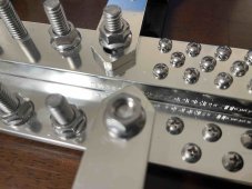
C) These little plastic tabs on the cover for the t-fuse holder will get in the way of the cables. I assume I just cut those tabs off as required?

Plastic piece.jpg

I was thinking about building a wall where the Quattro is recessed into the wall, so that its DC terminal line up on the same plane as the bus bar and the MPPT. That would allow for shorter cables and no bend.

But I think for now I'm just gonna slap it all up on the wall to start. Unless somebody tells me that 2 foot cables is not keeping it short enough. I'm using two sets of 4/0 for the Quattro, and 2 sets of 4/0 for the MPPT, so I think I've got plenty of copper to keep the resistance pretty low *I think*.

Many thanks for the words of wisdom. I'll standby to learn I bought the wrong bus bars for some reason...
 
Last edited:
Personally I would use the 24" cables with the inverter on top and the MPTTs below the busbar to keep the fuses spaced out a little more.

I am curious how much contact area you have on the fuse end of the busbar interconnects. By the looks of it I wonder if you would have better contact area with cable/lug.

That would be disappointing about the contact area. We got the bus bars, link bars, and fuse holders all from Blue Sea so was thinking they'd work together nicely.

Good idea about the fuses being spaced out more. I could put two up top and two down below. Something to consider for sure, many thanks.

link.jpg
 
That would be disappointing about the contact area. We got the bus bars, link bars, and fuse holders all from Blue Sea so was thinking they'd work together nicely.
The fuse side is the only one that looks a little questionable; the busbar side is better for sure.
 
Personally I would use the 24" cables with the inverter on top and the MPTTs below the busbar to keep the fuses spaced out a little more.

I am curious how much contact area you have on the fuse end of the busbar interconnects. By the looks of it I wonder if you would have better contact area with cable/lug.
Something like this? Then I could put the negative bar on the same level.

The only draw back I see is the design of the bus bar where the lower studs then make for a bad fit for the fuse holder since it's not level with it on that lower shelf. But I could rig up some boards and have the top fuser holders and the bus bar on the board so it's flush, and have the bottom fuse holders off the board to make those flush as well.
 

Attachments

  • two up two down.jpg
    two up two down.jpg
    340.2 KB · Views: 21
  • bad fit.jpg
    bad fit.jpg
    194.9 KB · Views: 21
Something like this? Then I could put the negative bar on the same level.

The only draw back I see is the design of the bus bar where the lower studs then make for a bad fit for the fuse holder since it's not level with it on that lower shelf. But I could rig up some boards and have the top fuser holders and the bus bar on the board so it's flush, and have the bottom fuse holders off the board to make those flush as well.
When you get done I’d be curious to know how much money you have in your buss system.
 
Looks good what are you going to use for protective covers on the buss bars?
It comes with these plastic covers. Like the fuse holders it has tabs that I assume I will just cut away so the cables can go through?cover.JPG
 
So I'm assuming I can put the positive and negative bus bars as close together as I can get them with the covers on, and I assume that those tabs are meant to be cut to allow for cable travel? There were no instructions with these things and the Blue Sea website FAQ doesn't have squat in it.
 
Actually I just wanted to see how close in cost it comes to my Lynx Power Ins. You are doing it right and there are 50 ways to skin the cat.

The wife says it was about $2300. That's for the two 1000A bus bars, 4 x ignition protected 400A t-fuse holders, 8 x ignition protected 200A fuse holders, 8 x 125A t-fuses, 2 x 300A t-fuses, 2 x 200A t-fuses and 6 link bars.
 
Personally I would use the 24" cables with the inverter on top and the MPTTs below the busbar to keep the fuses spaced out a little more.

I am curious how much contact area you have on the fuse end of the busbar interconnects. By the looks of it I wonder if you would have better contact area with cable/lug.

It looks like the lower terminals on the bus bar are .8" lower than the higher terminals. So I should be able to get a .8" thick board and mount the positive bus bar and top fuse holders onto that board, and then the bottom fuse holders would be off the board and so I think would line up flush with those lower terminals, if spacing out those fuser holders is something I should do.
 
Actually I just wanted to see how close in cost it comes to my Lynx Power Ins. You are doing it right and there are 50 ways to skin the cat.
We originally bought two Lynx. I was hoping to use them in our system. But then we learned that we should be using t-fuses and those don't fit on it.

So we'll use those Lynx when we finally get around to making a van build with 12V batteries.
 
Back
Top