diy solar

diy solar

JB Weld versus Loctite for grubscrews

Wet vs. dry threads while torqueing makes a large difference in clamping force. You can look up tables.
You could torque to spec, then apply loctitie.
If you want to do this more than once, considering the issue of stainless galling and siezing, might want to do it lubricated (possibly with loctite) and adjust torque value lower according to those tables. For other applications anti-seize is recommended.
Thanks. Planning on doing this only once. Thought about doing loctite after the fact, just not sure it really is necessary. If I double the nut on the end, really not worth it, I think. I am using nyloc nuts, after all.
 
So I just finally mounted the Helicoil into my stripped terminal.

Got a full 6 threads engaged out of which 4-1/2 threads of grubscrew engaged.

The post was off-square - with a nut hand-tightened down, I could see light and slip the thickness of two standard pieces of paper under that side. This was no-doubt due to the drill-press I used to enlarge the original hole being off-square.

I was mulling whether to try the ‘bent post’ technique to try to salvage the cell when I decided I might as well see how much torque the Helicoil could withstand.

At 25 inch-lbs, it started to slip and I can see that that the Helicoil is starting to pull out.

Looking inside, I can see that the top 4 Helicoil threads are pulling out while the lowest-two remain engaged.

So I’m not sure there is any sensible way to salvage this otherwise-good cell.
 
So after my setback with the Helicoil, I decided to try my hand at securing a grubscrew with Loctite Red.

Much, much, much easier and faster than JB Weld.

It’s so liquid it just leaks out all around the top thread as you screw in the grubscrew.

I wiped II the excess with paper towel but did not clean with Acetone as I’m worried the acetone will go down the thread and dilute/weaken the Loctite.

I used washers and nuts hand-tightened to hold the grubscrews vertical while the Loctite cures, but I’m interested in any cleaning advice.

It seems as though it takes 24 hours to cure with stainless at 25C (77F), and my cells are cooler than that (65F), so the curing time will be extended.

That’s not a problem for me but I’m interested in any advice as to how often I should remove the nut and washer to check for additional leakage and clean it up.

If the Loctite fully-cures, does it become impossible/much more difficult to clean off of the terminal surface?

Any advice on when it’s ‘safe’ to clean the terminal surface with Acetone appreciated...
 
I messed up a thread big time so i couldn’t even helicoil it. I jb welded a grubscrew in the hole, zero threads. It’s still working fine after 6 months, on high loads 125 amps it voltage drops 0.03v more than the others, and I don’t want to tighten it and risk it breaking. Doesn’t heat up so I don’t worry too much.
I found I had to use very fine sandpaper on all my terminals to stop voltage drop/heating up on ones that even looked ok.

edit: voltage drop wasn’t 0.2v
 
Last edited:
I messed up a thread big time so i couldn’t even helicoil it. I jb welded a grubscrew in the hole, zero threads. It’s still working fine after 6 months, on high loads 125 amps it voltage drops 0.2v more than the others, and I don’t want to tighten it and risk it breaking. Doesn’t heat up so I don’t worry too much.
I found I had to use very fine sandpaper on all my terminals to stop voltage drop/heating up on ones that even looked ok.

Interesting. I tried JB Weld on the stripped M6 hole and it came right out, but I’ve got nothing to lose trying again in the stripped M7 (Helicoil) hole.

Any idea how much torque you’re able to apply to that one JB Welded post? Finger-tight only or using a tool?

My maximum finger-tight torque is about ~20 inch-lbs (turning a socket using my fingers)...
 
i would guess partially tighter than finger tight, I did use a ratchet.
I used a torque wrench and initially was able to torque to 26.6 inch pounds (3nm). I recently found some of the nuts on my cells a bit loose so while I was tightening them down I tightened down the JB Welded stud a bit more. I don't want to risk tightening it any further. I did not use a torque wrench this time.
 
An update:

I tried JB Weld in the bigger hole, and it held all the way to 35 inch-lbs initially.

Despite my best efforts, the grubscrew was not perfectly straight and at 25 inch-lbs, I could still see a sliver of light through one side.

I’ve to 35 inch-lbs and the sliver of light disappeared (and the JB Weld seemed to be holding).

In switching lugs in an attempt to measure contact resistance at 35 inch-lbs, the JB Weld gave and the grubscrew pulled out (sheared the threads off).

So the good news is that JB Welded grubscrews in deep and large-diameter holes holds better than JB Weld in narrow short holes and appears to be able to sustain at least 25 inch lbs.

The bad news is that JB Weld doesn’t seem to be able to get to 35 inch-lbs at least on M6 threads.

I’m mulling what to do next and thinking about redrilling a 15/64” hole through the JB Weld (hopefully straight this time ;) and giving Helicoil-in-tapped-JB-Weld a try..

Now that I’ve understood how damaging larger hole sizes are to contact resistance, I’m only going to drill an M8 hole as a last resort:

13mm diameter terminal = 132.73mm^2

M6 hole removes 28.27mm^2 for 104.48 base contact area

M7 hole removes 38.48mm^2 for 94.25mm^2 contact area (90.2% or 111% base contact resistance).

M8 hole removes 50.27mm^2 for 82.46mm^2 contact area (78.9% or 127% base contact resistance).

I have no idea how to calculate the trade off between clamping force and contact area, but my gut tells me that 25 inch-lbs or hopefully 30 inch-lbs on 94.25mm^2 of contact area would probably be preferable to 35 inch-lbs on 82.46mm^2 of contact area (12.5% less)...
 
Do a gut-check by calculating clamping force, pressure, and looking up resistance per unit area in the linked graph.


Thanks, but I meant something different.

Greater clamping force results in a lower-resistance electrical connection between tinned lug and aluminum terminal, but only up to a point.

Increased contact surface also results lower electrical resistance in a direct (and linear) way.

So knowing that 35 inch-lbs on M6 is about the highest it makes sense to go in terms of clamping force (however many pounds that translates to @ M6), the question would be which is lower resistance:

25 or 30 inch-lbs on 94.25mm of contact
35 inch-lbs @ M6 on 82.46mm of contact (12.5% less contact surface)?

If increasing from 25 inch-lbs to 35 inch-lbs can reduce contact resistance by more than 12.5%, drilling a larger M8 hole and going that way may be best, but my gut feeling is that no reading torque from 25inch lbs to 35inch lbs is not going to reduce resistance by 12.5% (and in any case, I’ve got no way to measure contact resistance at these levels).

I suppose I could try to use current and measure voltage, at least to compare voltage drop at some reference current like 10A across the entire cell at:

-standard M6 thread @ 25 inch-lbs
-standard M6 thread @ 35 inch-lbs
-standard M6 thread @ 45 inch-lbs

-M6 thread in Helicoil in 15/64” hole @ 25 inch lbs
-M6 thread in Helicoil in 15/64” hole @ 30 inch-lbs (if I decide I need to push things that far).

Have you seen anyone else on the Forum who has attempted to characterize the impact of increased torque / clamping force on contact resistance to the terminal?

A ‘perfect’ 0 Ohm contact should result in ~150uOhm of Internal Resistance meaning voltage drop of ~1.5mV @ 10A versus 0A (at the limit of what my 1mV-precision DMM can measure).

When I’ve tried that dV/dI measurement before, I’ve seen much bigger voltage drops, either because the IR is much greater than 0.15mOhm or I made a crappy connection (or both).

But in any case, I should be able to notice reductions of contact resistance through increased clamping force if they are on the order of magnitude of the specified cell Internal Resistance.

Ever seen anyone try anything similar and/or measure IR using one of those IR meters through lugs / busbars clamped with different torques?
It almost sounds like you’re trying to blaze trails into the un-unknown.
 
It almost sounds like you’re trying to blaze trails into the un-unknown.

Wouldn’t be the first time ;).

On the other hand, the amount of clamping force / torque to apply to these 280Ah terminals has proven to be one of the most fragile and failure-causing attributes (often because the holes are tapped by hand and some to much shallower depth).

So before blindly torquing to 35 inch-lbs because someone said we should, it ought to be ‘known’ here on the forum what minimum level of clamping force / torque is truly needed in order to get contact resistance down to an acceptable level.

Of course there are other factors including cleaning any oxide off of the aluminum terminals surface that can have a significant impact on measured resistance / voltage drop, but there should be nothing ‘unknowable’ about the impact of torque/clamping force on the resistance of connections to these aluminum terminals (though it needs to be approached carefully to avoid measurements which have been thrown off by other factors).

There are those with a great deal more experience than me any many with far more accurate measurement equipment than I, and I’m still hoping I may find a thread somewhere where someone has already done this work.

But if I’m truly the first to raise this question, I’ll stumble along with what I have to actually characterize / confirm that there is enough of a reduction in contact resistance increasing torque from 25 inch-lbs to 35 inch-lbs to justify the increased risk of stripping terminal threads (especially of the shallow variety).
 
As long as you are using epoxy JBWeld is not really conductive.

How about something like this? Silver conducting epoxy

99% of the conductance is through the surface of the aluminum terminal into the surface of the lug/busbar (which is why the clamping force is important).

The material filling the hole as well as the conductance trough the voltage-grubscrew and back onto the top of the lug/busbar is immaterial (just look at the conductance of stainless steel compared to aluminum to confirm).
 
Mine is still holding at 3nm and I will not tighten it further. I am beginning to think the difference between 3nm and 4nm torque is negligible when regarding contact resistance providing everything is clean. But I have only run my battery at 850 watts so far. Conductive resistance could change when I up my testing to 1500 watts or so. Also I did not use any corrosion inhibiter yet and will be reassembling my pack with braided busbars. When I reassemble I might use MG Chemicals Carbon Conductive Paste.

The ends of the braided busbars are a tad bigger than the cells terminals so I am looking forward to that, but it might make measuring between the cells terminal and the contact area of the braided busbar difficult if not impossible. I do not want to have to take my pack apart again due to the risk of my JB Weld repair pulling up. Will be looking forward to your testing results.
 
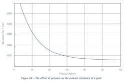
I’m on mobile otherwise I might go find it but there’s a thread in here somewhere with a graph of contact resistance versus clamping force and it shows a very steep drop off to nearly flat (meaning additional torque is nearly useless) at some point pretty early on.
 
I’m on mobile otherwise I might go find it but there’s a thread in here somewhere with a graph of contact resistance versus clamping force and it shows a very steep drop off to nearly flat (meaning additional torque is nearly useless) at some point pretty early on.

Here's a graph. (no units given for Y axis?)
I think it indicates area of contact isn't so important. Curve approximately says twice the pressure and half the area gives same resistance.
Force is important. For constant area, twice the pressure cuts resistance in half (approximately)

I think these terminals are before the knee of the curve, (which would be 20 N/mm^2.)
But "knee" is an artifact of how the data is graphed, which is basically "1/X" (resistance vs. pressure). If graphed as "X" (conductivity vs. pressure) I think it is roughly linear, no knee.
If I've got that correct, then 8mm thread is better than 6mm thread, for same material. (but 8mm steel insert in aluminum to provide 6mm steel thread would achieve the same, because steel is stronger; the 8mm aluminum thread is weakest link.)

I forget what force exactly the 35 inch-lbs worked out to.
Using 0.61 coefficient of friction (aluminum on steel, dry) 6mm diameter, 4 N-m torque, I get 1093N clamping force.

https://www.engineersedge.com/calculators/torque_calc.htm

1093 N clamping over 90 mm^2 area is 12 N/mm^2

Note!! Coefficient of friction for aluminum on aluminum is twice aluminum on steel.


If 4 N-m torque was the recommendation when vendor supplied aluminum bolts, using the same torque with steel threads in aluminum would produce twice the pull-out force. This could explain stripping of aluminum threads. It would also mean contact resistance with aluminum bolts would be increased.

If you're using steel on steel (nuts on grub screws), coefficient is 0.80, so 25% less force than aluminum with steel.
If brass on steel, coefficient 0.50 so higher clamping force.

1616940203429.png
 
Back
Top