diy solar

diy solar

JB Weld versus Loctite for grubscrews

Here's a graph. (no units given for Y axis?)
I think it indicates area of contact isn't so important. Curve approximately says twice the pressure and half the area gives same resistance.
Force is important. For constant area, twice the pressure cuts resistance in half (approximately)

I think these terminals are before the knee of the curve, (which would be 20 N/mm^2.)
But "knee" is an artifact of how the data is graphed, which is basically "1/X" (resistance vs. pressure). If graphed as "X" (conductivity vs. pressure) I think it is roughly linear, no knee.
If I've got that correct, then 8mm thread is better than 6mm thread, for same material. (but 8mm steel insert in aluminum to provide 6mm steel thread would achieve the same, because steel is stronger; the 8mm aluminum thread is weakest link.)

I forget what force exactly the 35 inch-lbs worked out to.
Using 0.61 coefficient of friction (aluminum on steel, dry) 6mm diameter, 4 N-m torque, I get 1093N clamping force.

https://www.engineersedge.com/calculators/torque_calc.htm

1093 N clamping over 90 mm^2 area is 12 N/mm^2

Note!! Coefficient of friction for aluminum on aluminum is twice aluminum on steel.


If 4 N-m torque was the recommendation when vendor supplied aluminum bolts, using the same torque with steel threads in aluminum would produce twice the pull-out force. This could explain stripping of aluminum threads. It would also mean contact resistance with aluminum bolts would be increased.

If you're using steel on steel (nuts on grub screws), coefficient is 0.80, so 25% less force than aluminum with steel.
If brass on steel, coefficient 0.50 so higher clamping force.

View attachment 42882
I just want to make sure my understanding isnt wonky. That is resistance for 1mm^2 of contact area. Correct? So if your contact area is 10mm squared, all of those square mms act as parallel contact points and thereby have the same effect as parallel circuits have on resistance? Or is that....wrong?
 
I just want to make sure my understanding isnt wonky. That is resistance for 1mm^2 of contact area. Correct? So if your contact area is 10mm squared, all of those square mms act as parallel contact points and thereby have the same effect as parallel circuits have on resistance? Or is that....wrong?

Yes, all in parallel.

Again, that chart doesn't have units. Can't be ohms, and seems to high even with milliohms. Maybe it is micro-ohms for something like tin-plated busbars, I'm not sure. I could imagine 5000 micro-ohms, 5 milliohms, for 1 mm of moderate pressure.
 
"Resistance (µ Ω) for 1mm^2"

"In everyday practice, contact pressure is impossible to measure and has to be inferred from the torque applied to the bolts from the following equation:"

Except, one member (@HRTKD ?) used a load cell to measure clamping force.

I think we need to revisit recommended torque. My observation of coefficient of friction for aluminum/aluminum being twice aluminum/steel and 50% more than steel/steel suggests that when people change screw material they are at risk of pulling out threads.
I believe a good calculation and measurement of force to yield for threads in terminals (or representative aluminum sample) would help in developing a revised value. Depth and tolerance of thread in terminal will be key.
Possibly looking for the minimum torque to provide the necessary connection vs the maximum torque allowed by the materials.
 
Possibly looking for the minimum torque to provide the necessary connection vs the maximum torque allowed by the materials.

My recent calculations suggest 50 micro-ohms with 4 Nm torque (but I'm using the copper busbar contact resistance figures, not aluminum or aluminum-copper contact.)
That is 20% of the 0.17 milli-ohm typical cell internal resistance. x2 contacts per cell, 40%

My examination of coefficient of friction suggests that if 4 Nm torque was good for aluminum on aluminum, then steel nut and steel grubscrew (don't have figures for stainless) should be 2/3 that torque for same clamping force (don't want to pull threads out). That puts contact resistance at 60% of cell internal resistance.

I think the necessary (or my desired) connection is under 10% of internal resistance, and I want torque of 16 Nm, but the cells can't take it.

Bypassing HRTKD's load cell, anybody can just measure contact resistance between two busbars while torquing stainless screws. Don't know how aluminum busbar contact resistance compares to pure aluminum terminal. Do it once without buffing off native oxide, then again buffed and dry, then again with oxide inhibitor.
The thing to do would be to run about 100A through the joint, and measure voltage with DMM leads attached close to the joint for 4-wire voltage sense.
 
Would be interesting to get that measurement at 1, 2, 3 and 4 Nm torque to see what is really achieved.
 
I'm not having the issues with terminals you other guys are. My SunXtender AGM batteries have 8mm threads in silicon-bronze terminals, and torque spec is 70 inch-lbs. That's twice the torque spec published for your aluminum terminals, and coefficient of friction for silicon bronze seems to be very low (haven't found specific values for this material, only other bronze). A different alloy phosphor-bronze is said to be self-lubricating. The bolts are brass. Figures I do find for coefficient of friction include phosphor-bronze/steel (0.35), bronze/cast iron (0.22). So I get twice the torque you do, and possibly 1/3 or 1/5th the coefficient of friction, for 6x or 10x the clamping force.

I think your only really good choices are welded busbars or welded on studs (use a dis-similar nut such as brass to avoid galling.)


My recent calculations suggest 50 micro-ohms with 4 Nm torque (but I'm using the copper busbar contact resistance figures, not aluminum or aluminum-copper contact.)
That is 20% of the 0.17 milli-ohm typical cell internal resistance. x2 contacts per cell, 40%

My examination of coefficient of friction suggests that if 4 Nm torque was good for aluminum on aluminum, then steel nut and steel grubscrew (don't have figures for stainless) should be 2/3 that torque for same clamping force (don't want to pull threads out). That puts contact resistance at 60% of cell internal resistance.

I think the necessary (or my desired) connection is under 10% of internal resistance, and I want torque of 16 Nm, but the cells can't take it.

Bypassing HRTKD's load cell, anybody can just measure contact resistance between two busbars while torquing stainless screws. Don't know how aluminum busbar contact resistance compares to pure aluminum terminal. Do it once without buffing off native oxide, then again buffed and dry, then again with oxide inhibitor.
The thing to do would be to run about 100A through the joint, and measure voltage with DMM leads attached close to the joint for 4-wire voltage sense.

So if I understand correctly, you’re saying 4Nm / 35 inch-lbs of Aluminum-on-aluminum should translate to 2.67Nm / 23.3 inch-lbs when torquing stainless into Aluminum.

I’ve successfully torqued my Loctited terminals to 35 inch-lbs and have torqued several of my JB Welded grubscrews to 45 inch-lbs, but I’ve confirmed JBWeld alone in a stripped hole without threads will sheer off the JB Weld threads at 35 inch lbs.

So it seems like 20 or 25 inch-lbs of torque on secured stainless Grubscrews is pretty manageable with these soft aluminum threads, 35 inch lbs is possible if you are careful, and 45 inch-lbs requires unnatural acts like Helicoils to achieve without stripping the aluminum threads.

Can’t someone translate those 3 torques to N/mm^2 so we can see where we are on that graph?

I can contribute with the denominator:

The overall terminal diameter is 18mm but the flat portion is only 16mm wide.

A terminal diameter of 16mm wide translates to an area 201mm^2.

The M6 hole in the center has a diameter of 6mm and an area of 28.3mm^2.

So the contact surface we are talking about it 201-28.3mm^2 = 172.7mm^2...
 
So here’s what I came up with (normalized to our 172.7mm^2 terminal surface:

25 inch-lbs on M6 stainless = 13.786 N/mm^2 for contact resistance of ~2500

35 inch-lbs on M6 stainless = 19.3 N/mm^2 for contact resistance of ~1600

45 inch-lbs on M6 stainless = 24.82 N/mm^2 for contact resistance of ~1100

Not knowing the units and taking the 35 inch-lbs value of 1600 as the baseline, this translates to:

25 inch-lbs = +56% of 35 inch-lbs
45 inch-lbs = -31% of 35 inch-lbs

I’d also like to understand what adjustment I should be making for brass nuts. If I understand correctly, brass is slightly ‘self-lubricating’ so 35 inch-lbs of torque on a brass nut on stainless threads applies more force than 35 inch-lbs of torque on a stainless nut on stainless threads...

OK, and now that I see the units are uOhm per mm^2, the 1600 @ 35 inch-lbs translates to 1.6mOhm / mm^2 or 9.3uOhms on our 172.7mm^2 terminal surface, or +12.4% for both terminals compared to Internal Resistance of 150uOhms.

25 inch-lbs 14.23uOhms or 19% of IR
35 inch-lbs 9.3uOhms or 12.4% of IR
45 inch-lbs 6.37uOhms or 8.5% of IR
 
I also looked it up and see that brass-on-steel has a coefficient of friction of 0.17 versus steel-on-steel which is 0.20.

When I factor that in, the grubscrews I’ve JB Welded in and torqued to 45 inch-lbs are actually delivering equivalent force to a stainless nut torqued to 63.5 inch-lbs (7.26Nm)

And the recently JB-Welded grubscrew that held at 35 inch-lbs for a few cycles but eventually pulled out was actually delivering equivalent clamping force to a stainless nut torqued to 41.125 inch-lbs (4.7Nm).

So I’ve been over-stressing my threads compared to all of you torquing to 35 inch-lbs with stainless nuts...
 
The issue I see with JB Weld (iron powder mixed with epoxy resin) is that it’s messy and tough to use in a situation where the part next to it has to be clean. The same is true of thread lockers. The liquid migrates (it only hardens in the absence of air) and gets on nearby parts. Most thread lockers will damage paint and plastics if not cleaned quickly.

Helicoils in aluminum are a better repair solution, just be sure to get a bottoming tap because the STI tap supplied with the consumer kits is a plug-style and doesn’t work well in shallow blind holes.
Not true at all. I mixed my jbweld on a piece of plastic. After I was done using it, I simply left the plastic sitting out. The epoxy left on it hardened while sitting in open air over night.
 
Not true at all. I mixed my jbweld on a piece of plastic. After I was done using it, I simply left the plastic sitting out. The epoxy left on it hardened while sitting in open air over night.
My comment covered two products — epoxy, and thread lockers like Loctite. They are not the same, and of course epoxy hardens in air.
 
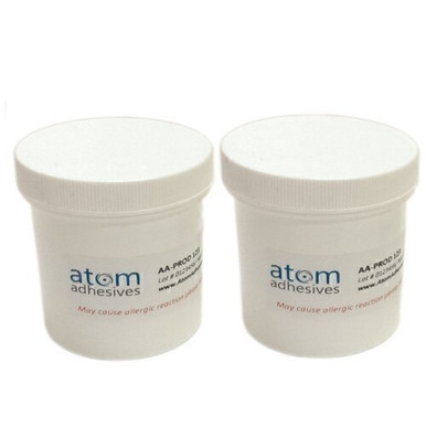
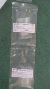
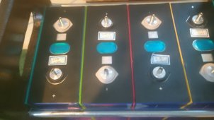
I went for the conductive epoxy, it placed nicely, squeezed up completely around the stud threads. I ordered 3 packettes, as I didn't know how far 2.5grams would go. Turns out one packette did 2 batteries (16 total,studs). Now I have two unused packettes..have no idea what I'll use them for LOL. ....and an extra 8 studs....
I'd rather have a conductive post, which then means a conductive top bolt&washers. This means both sides of a terminal lug are into contact with conductive surfaces. An analogy would be, why make a sandwich with only one slice of bread on bottom? You'd get mustard on your fingers, two slices of conductive bread are better!
 

Attachments

  • P_20210706_140844.jpg
    P_20210706_140844.jpg
    80.7 KB · Views: 17
  • P_20210706_140854.jpg
    P_20210706_140854.jpg
    202.6 KB · Views: 17
Last edited:
I went for the conductive epoxy, it placed nicely, squeezed up completely around the stud threads. I ordered 3 packettes, as I didn't know how far 2.5grams would go. Turns out one packette did 2 batteries (8 studs). Now I have two unused packettes..have no idea what I'll use them for LOL. ....and an extra 8 studs....
thank you for sharing!

conductive epoxy sounds really nice.

good going!
 
Sorry to open up the older post but I have questioned why there is so little concern about a conductive stud. Sure, maybe a stud does not add much, but I cannot believe it does not add something.

I'm too busy to do tests, but it would be curious if someone used a non conductive washer on the bottom of the lug and then did the testings on the resistance of the connection on the top. I bet the battery would still work and probably do a pretty good job. NO, I'm not suggesting this would be common practice or suggest that it would be better.There just seems to be so much speculation that the top part of the hardware does so little. I just believe the top should not be forgotten and does not seem to get a fair share of the press.

I plan on using Beryllium Copper round bar and cutting/treading to 6mm for the stud. I have a lathe and I've made one already. Using some type of silver conductive epoxy [have not decided which one] and a large copper top washer for the top. That should help with the current transfer. Although, this method may not help much, it certainly would not hinder and just provide a larger contact path for the current. I also understand that it may not be worth wild on low current battery systems.

I have read a lot of these pages but not all of them. Drilling studs to relief the pressure of the JB weld? WTF? How much are you installing on the stud? Using a small acid brush and applying the thinnest application will be enough. I do not think you could hand tight the stud in place with all the glue in the world and bust out the bottom. Of course, anything can happen. I do understand these are Chinese cells and it's probable that the holes are drilled so it's paper thin at the bottom. I just do not see that ever being a problem.

As an auto mechanic most of my life, I've taught the younger/newer techs that all the 'silicone' that has oozed out of a joint is the amount that was over applied. You should monitor that amount. Over time, you get an idea how much you really need and the quality of your work will improve. I would never fill a hole with adhesive. You paint the threads [not the bottom] of the stud. There is no reason for the bottom of the hole to have any adhesive either. You're wasting product and there is no purpose.

Of course, I'm new here, so I will just crawl under my rock and go away now.
 
why there is so little concern about a conductive stud
For me the simple answer is that the surface area of the cell terminal and the busbar provide enough conductivity for my current draw. I would rather use available materials and assemble my pack without being distracted by trivial concerns. I would rather focus on areas like conserving energy and improving the efficiency of other systems in my home. That is not to say there is no benefit to trying to get current to flow through a stud. I just have different priorities.
 
Back
Top