diy solar

diy solar

JBD 150A "Smart" BMS

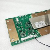
the 150a Bms is a beast. I suspect it’s upgraded mosfet silicon compared to the 100a version as they appear the same otherwise.

I’m interested why overkill is not selling the 150 unit as an option. Perhaps it’s a case of keeping a simplified and well tested 120a unit.

same logic is that the 120a version probably has upgraded silicon compared to the lower amp versions in the same pcb format.
 
..... additionally the B+ connection on these units seems optional ,to me it appears to be a convenient bus bar connection for positive . Apart from powering the BMS and reporting on the top battery channel as a duplicate if the red balance wire , does it serve any other purpose?
 
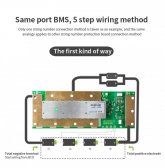
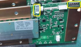
For my V1.3 boards, I concluded that the 5 pin connector (BC0, BC1, BC2, BC3 & BC4) is intended for pre-production testing and programming.

For operation, B-, B1, B2, B3 & B+ accomplishes all that the 5 pin connection does and avoids load current being carried on the tiny BC0 wire.JBD 150A wiring.jpg
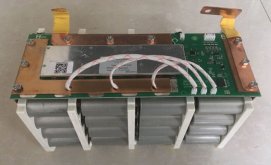
Here's a photo of a manufactured for sale to consumers battery using this BMS:
same BMS and not using 5 pin connector.jpg

and a video
 
Last edited:
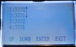
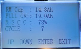
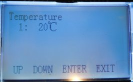
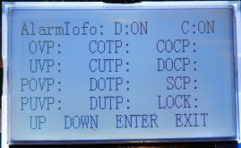
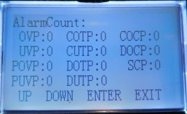
ShawnBest Store https://www.aliexpress.com/store/910438187 seems to have the newest JBD 150A BMS boards and accesories. They have V1.7 boards now, maybe make sure to request that if you want it. They also have the optional LCD display and the new green color JBD Bluetooth modules that have much greater range for my setup. I purchased the LCD from them. I use the green color JBD Bluetooth modules and the BT range is much greater the the blue BT modules I also have.

Bluetooth JBD.JPG
1.JPG
2.JPG
3.JPG
4.JPG
5.JPG
6.JPG
7.JPG
 
Last edited:
ShawnBest Store https://www.aliexpress.com/store/910438187 seems to have the newest JBD 150A BMS boards and accesories. They have V1.7 boards now, maybe make sure to request that if you want it. They also have the optional LCD display and the new green color JBD Bluetooth modules that have much greater range for my setup. I purchased the LCD from them. I use the green color JBD Bluetooth modules and the BT range is much greater the the blue BT modules I also have.

View attachment 40072
View attachment 40073
View attachment 40074
View attachment 40075
View attachment 40076
View attachment 40077
View attachment 40078
View attachment 40079
Great post. Straight to the pool room for that one....

a few questions;

Does the LCD screen include some toggle buttons for control ?

Can the backlight be turned off ?

Is it reasonably easy to mount the LCD with a dremel or similar?
 
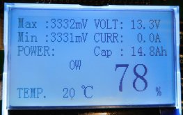
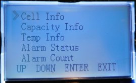
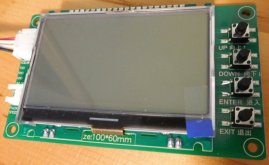
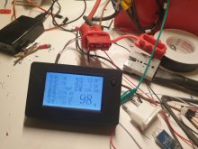
There are buttons for navigating through the screens. View only, no programming as far as I know. LCD turns off automatically after 20 seconds or so. Mounting it shouldn't be too difficult.

The supplied wire plugs into the Bluetooth / UART/USB connector. I don't know if that could be split to allow both LCD and Bluetooth at the same time. I don't have a use for it yet but thought I might in the future.
JBD LCD1.JPGJBD LCD2.JPG
 
There are buttons for navigating through the screens. View only, no programming as far as I know. LCD turns off automatically after 20 seconds or so. Mounting it shouldn't be too difficult.

The supplied wire plugs into the Bluetooth / UART/USB connector. I don't know if that could be split to allow both LCD and Bluetooth at the same time. I don't have a use for it yet but thought I might in the future.
View attachment 40183View attachment 40184
Thanx for that. Would be a nice addition to a battery. I think Bluetooth provides more data and control . The option is good to have.

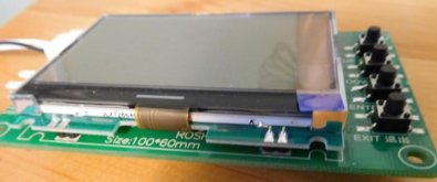
mounting may require some kind of film or cover to recess the buttons .

Great work finding this .

any other changes on the 1.7 ?

my 1.5 was supplied with three temp probes , but the software only shows two temperature readings .
 
These resistors or maybe diodes look new to V1.7:
V1.7_new.jpg

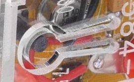
Re: mounting the LCD, there are tactile switch caps that could be used to raise the switch heights. I've also seen keyhole like cut-outs in acrylic that might work.

keyhole.jpg
 
These resistors or maybe diodes look new to V1.7:
View attachment 40243

Re: mounting the LCD, there are tactile switch caps that could be used to raise the switch heights. I've also seen keyhole like cut-outs in acrylic that might work.

View attachment 40248
I really appreciate the detail and photo provided.

yes, agree . I can’t work out their purpose. Perhaps additional balance current in an upcoming version.

another difference I’ve spotted . My 1.5 has two additional temp probes next to where your balance cable plugs in. And between your temp probe. Mine came with three, however software is reporting two temp channels.

button suggestion looks good.
 
Are the two additional temp probes between H+ & H-? (the two 4 pin pads for heater connection in the photo I posted)
 
Are the two additional temp probes between H+ & H-? (the two 4 pin pads for heater connection in the photo I posted)
Yes, those two four pin headers are populated on my 1.5 units with connectors.

two wires, center from memory go to the two temp probes, the two outer wires are terminated red/black.

the third temp probe is the same as yours.
 
V1.5 boards have a MOSFET that my V1.3 boards don't have. I wonder if the additional temp probes you have allow a heat pad to work? The MOSFET might cut or allow power through H+/H-. Have you tested H+ & H- with a voltmeter? If 0V then maybe try putting a temp probe in ice to see if that gets pack voltage at H+ & H-. It would be great to figure out how the heating function works on V1.5 & up boards.

V1.5 boards might have a built-in NTC on the board for BMS temperature. The other NTC probe would be for battery temperature. Just a guess but that would explain why the app sees two temperature sensors on your V1.5 board.

Do you use xiaoxiang 3.1.1026 app?
Currently using the payed apple iOS version .

im travelling with minimal tools for the next two months, possibly a delay in measuring that voltage . I’m keen to measure , however may not respond on that one until May/June .
 
No worries. Are the extra temperature probes you received built into the 4 pin wire connectors?
4 pin harness.jpg
 
Great info, that explains the heater connection wiring. Hopefully we'll find out the specific temperature trigger and heat pad wattage etc.
 
I've bought my display a few months ago, but it is in Chinese.. How did you set it to English?20210310_212627.jpg
 
When I inquired about the LCD, the store said it would be English version and when I ordered they asked how many cells in series then said "we will prepare the LCD display for you". I assumed that they did some setup before sending it to me but the messages were translated so that might not be correct. I don't know how to switch it to English.
 
Back
Top