diy solar

diy solar

JBD 200A 4S wiring

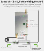
J8 (H-) is the heating port. If/when the low-temp cut-off activates (adjustable via Charge Under Temp in the BT app) any charge current will be routed here instead of the cells. I believe the current for this port is limited to <8a.
 
Last edited:
It if a revive on this, but the manual I found was not all that helpful. Anyone know what the extra two wires are for? View attachment 113553

One clearly is sized for j2 (discharge interface), since the manual is not really clear I thought I’d ask to confirm.

The second one (with the two black wires) looks like a sensor of some type. Thoughts?

Is there a use for J8? (H-)
View attachment 113554
J8 is where you attach the heating pad (I've never used it). The heating pad is switched on and off by the BMS depending on the temperature you set. The two wires attached to just a connector is to install a switch, used to enable/disable the BMS output. As someone already told you, the sensor is for over temperature protection, the two under temperature sensors are already attached and they use silicone to make sure they don't accidentally unplug.
 
Maybe this will help, reinforce what the others have been saying.
 

Attachments

  • Screen Shot 2022-07-28 at 8.30.56 PM.png
    Screen Shot 2022-07-28 at 8.30.56 PM.png
    553 KB · Views: 55
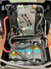
Hey, thanks for the feedback. Here is an internal shot. (still a little cleanup to go, but super fun.) I have a friend helping on the build, since this is my first one.

2DE450FE-D70B-4702-847F-3837EB2C98B3.jpeg

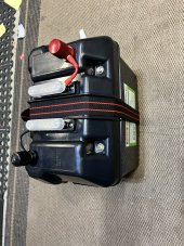
@Reigate thanks also for the mount I used it to mount it to a steel plate. The other side has a Victron shunt and 100 amp fuse. I also picked up small automatic battery heaters and put them in the box. In all it makes for a nice 160 AH battery.

F0C0B72E-199D-411A-A7DA-DCB7B5A8BBBF.jpeg
 
Last edited:
I would relocate the Bluetooth transmitter to a plastic surface.
Where it is now will block signal
I thought it might block the signal as well, but its actually better than my 12 | 800 Victron Dongle. I get a great signal when the battery closed up.
 
Ref the heating pad circuit on our JBD 200a BMS. Ambient temps dropped to 15f this morning. Cell temps had dropped below the charge and discharge cold/low temp cut-off presets. We applied charge current to activate the heating pad circuit on the BMS. No-go. We had to turn on the discharge mosfet to get charge current to flow to the heating pad (H-) terminal on the BMS.

Is this SOP for the JBD 200a BMS?
 
Last edited:
In reading the specs on this BMS it appears that the range for LVC is only 2.4 - 2.6v/cell. I like to set mine higher at 3.0v/cell. Can this be done or will I be limited to 2.6v/cell for the max value of LVC?
 
In reading the specs on this BMS it appears that the range for LVC is only 2.4 - 2.6v/cell. I like to set mine higher at 3.0v/cell. Can this be done or will I be limited to 2.6v/cell for the max value of LVC?
Can't imagine why it would be limited to 2.4v - 2.6v. Have you tried adjusting it 3.0v to see if the BMS will allow it? We have our JBD 200a set to 2.700v with no issues. Discharge mosfets open immediately when voltage on any cell drops below 2.700v.
 
Last edited:
Can't imagine why it would be limited to 2.4v - 2.6v. Have you tried adjusting it 3.0v to see if the BMS will allow it? We have our JBD 200a set to 2.700v with no issues. Discharge mosfets open immediately when voltage on any cell drops below 2.700v.
My two batteries are still on the slow boat from China but that is one of the first things I will do.
 
Back
Top