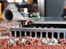
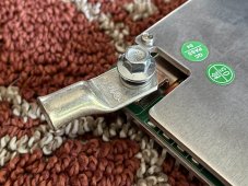
I’ve ordered a JBD 200A 4S SP04S034. While I’m waiting for it to arrive I’m trying to order all the appropriate wiring and connectors. Can anyone confirm what size lugs I’ll need on the wires to the B- and C- pads? M6/M8/M10? I assume bolts are provided with the BMS to attach.

I asked JBD this question and support’s answer was “24AWG” which doesn’t answer my question but also seems to suggest a dangerously undersized wire for 200A of current - what am I missing here?
I asked JBD this question and support’s answer was “24AWG” which doesn’t answer my question but also seems to suggest a dangerously undersized wire for 200A of current - what am I missing here?