diy solar

diy solar

JBD and external loads

Aphers

New Member
Joined
Nov 17, 2020
Messages
212
Asked this already on another section of the forum but no takers, so apologies for repeating it here.

I have a JBD BMS (same basic idea as Overkill). 120A. I would like to run an inverter and control it via its remote switching port. From what I've read I can't really do this using the JBD, but there is a workaround possible where I put a relay in line with the negative bus and it would trip whenever the BMS trips. I'm probably describing that very poorly. The downside is that the power going to the inverter no longer passes through the JBD's shunt so the SOC readings would be way off.

Other than needing to add a battery monitor to know what my true SOC is, will this setup cause any other problems? And (short of buying a different inverter or BMS) are there any other ways to design the system that would be better?
 
You would also loose over current protection from the BMS.

Why not just use a contactor based BMS that is designed for this?
 
You would also loose over current protection from the BMS.
Good point, thanks. But I'm not too worried about that, at full whack the inverter's draw is still under 1C. If something shorts the supply will be fused as well. Thirdly, the inverter itself has over-current protection.
 
You would also loose over current protection from the BMS.

Why not just use a contactor based BMS that is designed for this?
If you have an inverter that has two inputs to discriminate between switching of charging and switching of loads you need B- and C- and P- terminals to switch two donkey relays or optocouplers. If you don't have a P- output, then you have to switch everything at once.
Caveat: I haven't tried this but it should work.
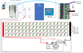
Just before the inputs to FETs there are shunt resistors on the PCB, they create a small voltage drop proportional to the current and its direction.
The app allows you to calibrate this shunt against this tiny voltage. If you scratched these resistors to be open circuit, you could feed in a shunt voltage from your own external shunt and calibrate the BMS to this new shunt.
Then you would keep Overcurrent protection and SOC.
This is a design I was thinking about, I have already decided to do ther things but I think it covers what you want.
Remember this design has never been tested.

1621883117183.png
 
That's quite an interesting approach... possibly a bit out of my comfort zone though. If I take the simpler route of adding a battery monitor, and with the caveat that the inverter wouldn't ever draw more than 1C, would the BMS/cells be at any sort of risk due to the load that it can't 'see'?

I can live with the hassle of cutting off charging and loads together, the inverter will only be used for short periods with someone in attendance.
And is your charging capability equally limited?
 
You haven't said what 1C is but if you're happy with this then if you are fused at the battery you should be OK.
 
You haven't said what 1C is but if you're happy with this then if you are fused at the battery you should be OK.
They're 272Ah cells, inverter would be 250A max. I plan to limit actual usage to about 170A, just slightly over-sizing the inverter in the hope that it will last a bit longer (and the next size down is too small for me anyway).
 
Back
Top