diy solar

diy solar

JBD AP21S002

Jaxonwood

New Member
Joined
Jun 25, 2022
Messages
29
I am connecting balance leads and missing clear guidance on the connection for the last cells in a 16S.
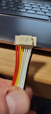
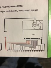
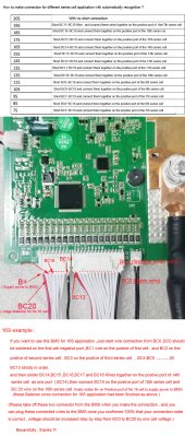
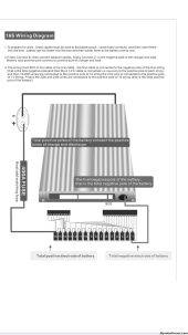
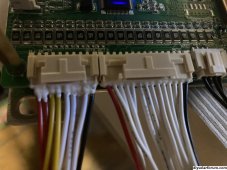
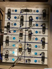
Anybody know how this goes? The first connector seems clear enough and takes care of cells 1-13. But I have no 16S guidance on this 2nd nine wire for the last three cells. I think it's easy for cell 14 with the black wire, and also with the next white wire for cell 15. My interpretation of the JBD documentation is to connect both red wires to cell 16. Thoughts?
 

Attachments

  • 20221228_213955.jpg
    20221228_213955.jpg
    81.7 KB · Views: 22
That's correct, once I read the instructions 800000 times and found a diagram here, it made sense.
Should be able to see mine together if you zoom in.
 

Attachments

  • IMG_20221024_194454.jpg
    IMG_20221024_194454.jpg
    393 KB · Views: 149
Perfect! Thank you!
No problem, found the diagrams I had saved if you haven't wired it up yet.
Don't forget to check each pin before plugging into the BMS, voltage should step up on each one as you go to the end.
 

Attachments

  • BMS wiring .jpg
    BMS wiring .jpg
    94.3 KB · Views: 176
  • BMS Connection-AP-1.jpg
    BMS Connection-AP-1.jpg
    258 KB · Views: 140
I am connecting balance leads and missing clear guidance on the connection....
I have the same model. So far mine communicates with BT on an 8S mockup battery using a power supply and resistors. What I can't get working is the RS485 option. The connector is there but it appears there are no components populated around it.

Do you have that option? Can you post a picture of the area around it?
Found the issue. The port is labeled RS485 but it's actually just another ttl UART
 
I just received this same BMS with no documentation. building 48v 16s battery for golf cart, My question does lead 15-19 get capped off or are they also connected to cell 14?

Thank you
 
thank you, I finally received diagram from supplier. with instruction to connect leads 14-19 to cell 14.
 

Attachments

  • 16s JBD BMS diagram.pdf
    440.5 KB · Views: 109
Hi, having issue with the same JBD AP21s002.
Shows incorrect voltage for first 2 cells.
Checked all connections an recrimped first 3 (+) wires but it did not solved the problem.
For 9pin connector, I followed manual and connected 14-19 wires to cell14, next yellow wire to cell 15 and two red wirres to cell16.
Does it mean that problem is with first two cell connecton or can be also with cells 14-16 connection.
Please check maybe someone will find a problem from pictures.
 

Attachments

  • IMG_5724.png
    IMG_5724.png
    216.7 KB · Views: 13
  • IMG_5723.jpeg
    IMG_5723.jpeg
    1.4 MB · Views: 11
  • IMG_5722.jpeg
    IMG_5722.jpeg
    878.6 KB · Views: 16
  • IMG_5721.png
    IMG_5721.png
    283.6 KB · Views: 11
Hi, having issue with the same JBD AP21s002.
Shows incorrect voltage for first 2 cells.
Checked all connections an recrimped first 3 (+) wires but it did not solved the problem.
For 9pin connector, I followed manual and connected 14-19 wires to cell14, next yellow wire to cell 15 and two red wirres to cell16.
Does it mean that problem is with first two cell connecton or can be also with cells 14-16 connection.
Please check maybe someone will find a problem from pictures.
Uptating my self.
Main B- cable from BMS was not connected. After connecting it all went well. ?‍♂️
 
For 9pin connector, I followed manual and connected 14-19 wires to cell14, next yellow wire to cell 15 and two red wirres to cell16
Hi, having issue with the same JBD AP21s002.
Shows incorrect voltage for first 2 cells.
Checked all connections an recrimped first 3 (+) wires but it did not solved the problem.
For 9pin connector, I followed manual and connected 14-19 wires to cell14, next yellow wire to cell 15 and two red wirres to cell16.
Does it mean that problem is with first two cell connecton or can be also with cells 14-16 connection.
Please check maybe someone will find a problem from pictures.
I have read the instructions and shouldn't 14 to 20 be crimped together? 20 being the first yellow wire. then the next yellow wire ( 21 ) goes to cell 15 then the two reds to16. I am wiring mine right now and want to be sure I do it right.
 
For 9pin connector, I followed manual and connected 14-19 wires to cell14, next yellow wire to cell 15 and two red wirres to cell16

I have read the instructions and shouldn't 14 to 20 be crimped together? 20 being the first yellow wire. then the next yellow wire ( 21 ) goes to cell 15 then the two reds to16. I am wiring mine right now and want to be sure I do it right.
Anyone?
 
Got the two harnesses wired up. Looks good on the app. Their are 3 two wire harnesses left. I can see where they fit on the BMS , but where does the other end go ?
 
Got the two harnesses wired up. Looks good on the app. Their are 3 two wire harnesses left. I can see where they fit on the BMS , but where does the other end go ?
Can you post a photo of them. I'm pretty sure they are for an optional switch.
 
I think they must need to be hooked up because no current is going in or out of the BMS
I don't think you need them. I didn't use any that look like that.

Do you have proper cell voltages? Did you check with a meter before connecting?
Did you enable charge and discharge in the app?
 
Yes the app shows cell voltages I checked harness with meter for voltage and correct order before hooking up. The app shows green for charge and discharge.
1708564676998.jpeg
 
Back
Top