spidgrou,
here are the steps I used to install jbdtool on the RPi (assuming it's connected to internet).
clone jbdtool source on RPi (from ssh login to RPi)
pi@hassbian:~ $
git clone https://github.com/sshoecraft/jbdtool.git
download and install pahomqtt c, jbdtool uses the library for mqtt support.
pi@hassbian:~ $
git clone https://github.com/eclipse/paho.mqtt.c.git
pi@hassbian:~ $
cd paho.mqtt.c (go into the folder where the git repository was copied down to.)
pi@hassbian:~/paho.mqtt.c $
make (this should do some things and finish without errors)
pi@hassbian:~/paho.mqtt.c $
sudo make install
make & install jbdtool
pi@hassbian:~ $
cd ~/jbdtool (go into the folder where the git repository was copied down to.)
pi@hassbian:~/jbdtool $
make
pi@hassbian:~/jbdtool $
sudo make install
success?!?! type jbdtool from any location, and it should list all the input arguments available. Then try the ip connection to the ESP/UART BMS
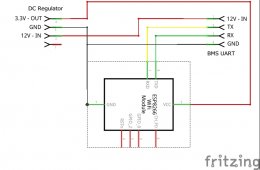
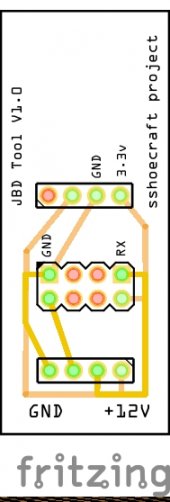
Another thing to check, after setting up the esp8266 mini with esp-link, can you ping it's ip address from the RPI, and from a browser on your network, can you see the esp-link configuration page, and completed the settings so it will function as a serial wifi bridge? I think only the uart should be connected to the esp8266, not the usb to something else except maybe to power it? Are you using a 3.3v supply to power the ESP from the BMS UART, or powered from the usb? I guess an esp8266 mini is like an ESP01 but with an FTDI type usb chip permanently attached, and the usb plug can power it and reprogram it. This is a little different than using the very minimal ESP01 board. I guess it should work, but maybe something in esp-link may need to be set differently.