diy solar

diy solar

JBD / Overkill BMS 120A 4S Lifepo4 in series / parallel

Battery line series inductance is reduced if you parallel tape together pos and neg cables, which reduces ringing. This also put less stress on inverter input bypass electrolytic capacitors and inverter switching MOSFET's.
Oh this is interesting, do you twist them too or just side by side?
 
Oh this is interesting, do you twist them too or just side by side?
Pretty hard to twist large gauge. Twisting does not lower impedance much. Twisting is primary used to cancel common mode external interference pickup which is not much of a consideration for battery lines.

Swisting the shunt sense wires going to battery monitor which are small gauge and carry weak current sense voltage does make good sense.

I had a metal box I mounted my inverter battery line breaker in. First I put pos and neg battery cables through metal box with pos going through breaker and neg line going around the side of breaker. It was fine.

Later I put in a second inverter and another breaker in the metal box next to the first breaker. Not having enough room with the second breaker I ran the negative battery cables around the outside edge of metal box. After that I noticed a buzzing sound. It was the metal box door which fit loosely reacting to the single cable magnetic field created by the 120 Hz battery line ripple current. On the first single breaker with both pos and neg lines running through the box the fields cancelled and there was no buzzing.
 
Last edited:
If you use a BMS in a series battery array that is above its MOSFET switch breakdown voltage you will not know until cutoff is needed. As long as switch stays closed it will not show any problem.

If it has a bms cutoff for some reason the shutoff MOSFET can avalanche (like zener), gets very hot and either blows open or short. Usually its goes shorted meaning the BMS does not cutoff when it should.

Is it worth putting your batteries at risk if BMS does not shut down when it is needed to.

The cost of MOSFET's goes up for low Rds_ON and higher Vds_breakdown. Above 40v breakdown the cost of low Rds_ON resistance MOSFET are much higher so BMS's for 4s and 8s may all use 40v breakdown MOSFET's just so manufacturer does not have to source two different parts.

Really have to be careful of cheap 12v LFP batteries. They are striving to squeeze every penny of manufacturing cost out of them so may use 25-30v breakdown MOSFET's in their internal BMS. If their specs do not specifically state they are stackable assume they are not.

For 16s BMS, 80v breakdown is minimum, 100v breakdown preferred. With long pos and neg separated battery cables there can be voltage ringing.

Battery line series inductance is reduced if you parallel tape together pos and neg cables, which reduces ringing. This also puts less stress on inverter input bypass electrolytic capacitors and inverter switching MOSFET's.
JBD started by manufacturing BMS for medical devices. When they advertise 80v rated parts, I believe them. I haven't asked them about their new 200 amp 12v BMS yet, it may or may not be rated for 80v. With the current parts shortages who knows what they are actually receiving, but their note about qualifying substitute parts is encouraging.
 
Last edited:
Pretty hard to twist large gauge. Twisting does not lower impedance much. Twisting is primary used to cancel common mode external interference pickup which is not much of a consideration for battery lines.

Swisting the shunt sense wires going to battery monitor which are small gauge and carry weak current sense voltage does make good sense.
What would you twist the sense lines with? One each per cell. You might get some inductance if they are close to A/C, but they really aren't carrying any signals.
 
What would you twist the sense lines with? One each per cell. You might get some inductance if they are close to A/C, but they really aren't carrying any signals.
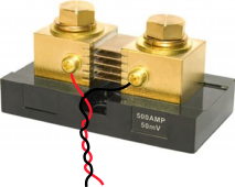
How many battery current shunts do you have? ( I have 11 current shunts. One 100A shunt on each of 10 parallel 48v battery packs and one 500A shunt for total current going to inverters, all with twisted pairs to shunt sense wires. )

Twist each pair for each battery shunt sense wires. If you have them running near and in parallel with battery lines they can pick up the 120 Hz ripple current from a 60Hz sinewave inverter battery lines. There can be a phase shift between the 120 Hz ripple from the shunt pickup and the coupled 120 Hz ripple picked up from running shunt sense lines near battery lines. This can give an error in monitor current reading that will change in value if the spacing between battery cable and current sense wires changes.

The 120 Hz ripple current peak to peak value in battery lines is greater than the average DC current to inverter.

Battery monitor have a couple Hz low pass filter either as R-C filter or digital low pass filter in microcontroller to average out the 120 Hz ripple current.

I think this is hijacking the thread.
 
Last edited:
How many battery current shunts do you have? ( I have 11 current shunts. One 100A shunt on each of 10 parallel 48v battery packs and one 500A shunt for total current going to inverters, all with twisted pairs to shunt sense wires. )

Twist each pair for each battery shunt sense wires. If you have them running near and in parallel with battery lines they can pick up the 120 Hz ripple current from a 60Hz sinewave inverter battery lines. There can be a phase shift between the 120 Hz ripple from the shunt pickup and the coupled 120 Hz ripple picked up from running shunt sense lines near battery lines. This can give an error in monitor current reading that will change in value if the spacing between battery cable and current sense wires changes.

The 120 Hz ripple current peak to peak value in battery lines is greater than the average DC current to inverter.

Battery monitor have a couple Hz low pass filter either as R-C filter or digital low pass filter in microcontroller to average out the 120 Hz ripple current.

I think this is hijacking the thread.
I assumed you were speaking of voltage sense wires on the BMS. I had no clue you were speaking of shunts.
 
I assumed you were speaking of voltage sense wires on the BMS. I had no clue you were speaking of shunts.
No, I mean the current shunt sense wires. You cannot do anything about the BMS cell voltage sense wires as they are shared between two cells. You could use shielded wire but that only gives capacitive coupling interference protection.

If you are using BMS for current reading you may not have a separate battery monitor and associated current shunt.

500 amp 50mV shunt.png
 
Last edited:
No, I mean the current shunt sense wires. You cannot do anything about the BMS cell voltage sense wires as they are shared between two cells. You could use shielded wire but that only gives capacitive coupling interference protection.

If you are using BMS for current reading you may not have a separate battery monitor and associated current shunt.

View attachment 68669
We were speaking of BMS being rated for series use. I didn't know you had switched to talking about shunts.
 
Since I'm on the right laptop now, here is the spec sheet for the 200 amp JBD (and I have NOT asked if it is capable of series connection).

And the specific parts listed do look like a 40v rated part. But then again, they don't claim this model BMS is capable of series connection. Higher voltage rated parts are more expensive.

Spec sheets for both parts (note the spec sheets are in English).


Attachments

  • JBD-SP04S034-L4S-200A-200A-B-U V1 0 zh-CN en.pdf
    2.2 MB · Views: 13
Last edited:
the reason you could do 2 in series like in a RV. you can not put them all in on box due to space available
SP04S028A is the only Jiabaida model that can be parallel and not more than 4p. The other models are not designed to be parallel. This info received from the engineer at Jiabaida.
 
Back
Top