diy solar

diy solar

JBD / Overkill BMS getting warm when "charging port off"

squowse

Solar Enthusiast
Joined
Jan 4, 2021
Messages
581
Have only had solar panels for a few weeks. I've been looking at ways to stop them overcharging the cells in a 4S pack. The cells go a bit out of balance at the top and will trigger high cell voltage repeatedly.

I've started switching off "the charging port" on the BMS using the Xiaxong app on iphone. Switch off when the battery is fully charged and then switch on again in the evening.

I noticed that the internal BMS temperature rises 5-10 degrees C by the end of the day. Seems like it is actively working to close "the charging port". The BMS only has two wires - eg it doesn't actually have separate charge and discharge ports. So I suppose this is why it generates heat? Working to keep it closed to charge but allowing discharge?
 
Not an answer to your questions but....
1. Don't you have a way to set the charging voltage on your charger?
2. In the BMS settings you can set (under protection section as I recall) the max volts per cell. So you can let the BMS cut charging off when any once cell hits 3.6v (for example).
 
As @DThames alluded, you're doing it wrong. The charger should be where you make the changes to ensure that you get the charge profile you want. The BMS is the last line of defense should your charge device(s) go crazy.
 
Reduce the charging voltage on the chargers . Any voltage over 13.8 will be enough to charge, try 14.0 volts ( assuming a 12v system).

It's possible the cells are not top balanced, did you miss out this step when building the battery?

Mike
 
Have only had solar panels for a few weeks. I've been looking at ways to stop them overcharging the cells in a 4S pack. The cells go a bit out of balance at the top and will trigger high cell voltage repeatedly.

I've started switching off "the charging port" on the BMS using the Xiaxong app on iphone. Switch off when the battery is fully charged and then switch on again in the evening.

I noticed that the internal BMS temperature rises 5-10 degrees C by the end of the day. Seems like it is actively working to close "the charging port". The BMS only has two wires - eg it doesn't actually have separate charge and discharge ports. So I suppose this is why it generates heat? Working to keep it closed to charge but allowing discharge?
What are the settings in your solar charge controller?
 
Thanks. I'm aware of all of the above.

If anyone has any insight into how the bms works and why it generates heat to switch off the "charging port” I'll be interested.
 
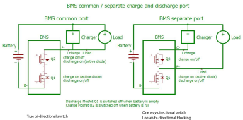
Many dual port BMS's just tap split the back-to-back MOSFET's. This means you lose bi-directional switching.

When load port is off, if you apply any charge into the load port it will pass through the body diode of the load port MOSFET switch. If there is reverse charge current applied to the load port, the extra voltage drop of the body diode of the load port MOSFET will cause it to get hot.

This can also happen to charge port if you have a load on charge port when charge port is turned off. This is likely your situation.

On a dual port BMS if you charge into load port there is no cutoff protection for cell overvoltage. This is why I don't recommend anyone buy a dual port BMS. Most chargers are fine sitting in parallel with load and when the charger is off it does not consume any current. The dual port BMS will not stop a charger from draining battery when it has leakage current when it is turned off.

Big time screw up is a setup with PV SSC going into separate port BMS charge port and an inverter/charger on BMS load port with inverter/charger having battery charging enabled. Inverter/charger when charging may not have BMS cell overvoltage shutdown protection.

Overheating can also happen on common port BMS if it has user control for disabling charge or discharge but they typically monitor the BMS current and override the user setting and turn both back-to-back MOSFET's back on when current gets more than a few amps to prevent MOSFET overheating.

BMS-common-separate-port.png
.
 
Last edited:
Thanks - that's really interesting.

So in my case (the left diagram). When the "charging port" is switched off the then the discharge is flowing through diode Q2, not the MOSFET.
My knowledge of diodes is that there's a small voltage drop, and this could generate some heat?
 
Thanks - that's really interesting.

So in my case (the left diagram). When the "charging port" is switched off the then the discharge is flowing through diode Q2, not the MOSFET.
My knowledge of diodes is that there's a small voltage drop, and this could generate some heat?
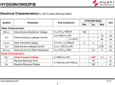
The body diode will have 0.8 to 2v of voltage drop depending on current and MOSFET temp. If you have a common port JK BMS with user control to turn off charging then discharge current is flowing through one of the MOSFET body diodes.

If you have 1v drop on body diode and 5 amps of discharge current you have 5 watts of heating on MOSFET. This will cause BMS to get a bit warm. I used 5 amps because this is close to amperage where the JK BMS will override your charge disable function and turn both MOSFET's back ON to reduce voltage drop across switch.

The JK BMS will re-disable charging when load current drop below about 5 amps. Same applied for discharge disabled function on charging current.

There is a bit of time for JK BMS to measure the current and its direction of flow to make the decision to override or re-enable your disable setting. If inverter load current and charge current is varying and overlapping in absolute current level, the BMS may see positive charging current or negative discharge current randomly. The little bit of time it takes for making the override decision may add a little more heating to body diode due to the short periods of higher current through body diode.

It may be earlier versions of BMS firmware did this by MOSFET temp reading, instead of current measure. Basing override on MOSFET temp is really slow reacting.

HYG035N10NS2P mosfet.png
 
Last edited:
Brilliant explanation. I suppose my niggling worry is that it's not a good thing for the longevity of the BMS to have this discharge through the diode creating heat?
 
the explanation from RCinFLA is really good.
To solve your problem with your current BMS, set the Over voltage releas flag to be just a few mV lower than your over voltage protection values. so If your Over Voltage protection is set to 3.6V set the releas Over voltage protection to 3.55V What will happen is that when the battery is fully charge, it will disable the charging port, and when you conect a load it will remain disable but just for a little bit and then re-enable charging port which in turn will prevent the over heating
 
Back
Top