diy solar

diy solar

JK 200A active balancing BMS battery current limits

RCinFLA

Solar Wizard
Joined
Jun 21, 2020
Messages
3,563
I did a thermodynamic simulation some time back on the 16S/24S JK active balancer BMS. I was not confident in my thermal resistance calculations on the irregular MOSFET epoxy plastic topside surfaces. Then I saw Andy's (Off-Grid Garage) video where he smoked the new 4S/8S JK BMS, drawing about 210 amps to charge his Tesla so I decided to update the original 16S BMS simulation to the new but similar 4S/8S BMS.

Using Andy's data point where he smoked the BMS with 210 amps I checked my simulation, and it was pretty close to showing the same 'smoke' point.

As with most of the Chinese BMS's, the main issue is poor heat transfer from MOSFET's due to using the epoxy plastic case side of MOSFET's to dissipate heat. It creates a big temp difference between MOSFET temp and heat sink temp due to the thermal resistance going through MOSFET epoxy plastic case. Even if you replace the flat aluminum case plates with heat sink fins cover plates it will not help much on reducing maximum MOSFET temperature.

These simulations (both models) are for continuous load current with 25 deg C ambient air temp. Short period peak load current temp rise is a lot tougher to simulate.
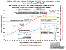
JK 4-8S active balancer BMS temp vs current.pngJK 16-24S active balancer BMS temp vs current.png
 
Thanks for posting this. So basically people should configure in the app max discharge for the 16S/24s 125A and 150A for the 4S/8S and shut down if staying X seconds over that. It would also help if we could use multiple banks in parallel with multiple JK BMS's to spread the amps across them but since they don't recommend us doing that for some reason we are left in a pickle.
 
I was not confident in my thermal resistance calculations on the irregular MOSFET epoxy plastic topside surfaces. Then I saw Andy's (Off-Grid Garage) video where he smoked the new 4S/8S JK BMS, drawing about 210 amps to charge his Tesla
I saw that Andy clip too. ... IMO: (going by my memory) ...the BMS triggers were adjusted (I think by default) ... for a 300 seconds "Delay". IMO: If that Delay had been adjusted to a 10 seconds ... we would Not have seen the burn out smoke. Why 300 seconds for trigger release delay ???
 
Last edited:
I did a thermodynamic simulation some time back on the 16S/24S JK active balancer BMS. I was not confident in my thermal resistance calculations on the irregular MOSFET epoxy plastic topside surfaces. Then I saw Andy's (Off-Grid Garage) video where he smoked the new 4S/8S JK BMS, drawing about 210 amps to charge his Tesla so I decided to update the original 16S BMS simulation to the new but similar 4S/8S BMS.

Using Andy's data point where he smoked the BMS with 210 amps I checked my simulation, and it was pretty close to showing the same 'smoke' point.

As with most of the Chinese BMS's, the main issue is poor heat transfer from MOSFET's due to using the epoxy plastic case side of MOSFET's to dissipate heat. It creates a big temp difference between MOSFET temp and heat sink temp due to the thermal resistance going through MOSFET epoxy plastic case. Even if you replace the flat aluminum case plates with heat sink fins cover plates it will not help much on reducing maximum MOSFET temperature.

These simulations (both models) are for continuous load current with 25 deg C ambient air temp. Short period peak load current temp rise is a lot tougher to simulate.
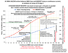
View attachment 95736View attachment 95737
Nice work !
 
I saw that Andy clip too. ... IMO: (going by my memory) ...the BMS triggers were adjusted (I think by default) ... for a 300 seconds "Delay". IMO: If that Delay had been adjusted to a 10 seconds ... we would Not have seen the burn out smoke. Why 300 seconds for trigger release delay ???
Andy did not "set" it to 300 seconds. That was the default setting and JK rates it at instantaneous max of 350A and 200A for 300-seconds.
Not saying this is prudent but his purpose was to test the limits not prudent settings. I am happy for him to blow up the first model if it gets me the info I need to make mine have a long and problem free life.
 
Back
Top