Hans Kroeger
New Member
- Joined
- Dec 30, 2020
- Messages
- 128
I bought 2 displays to be used with my JK-B2A8S20P modules...... and I am not happy with their performance.
1. The display shows the Balancer to be on at all times, independent of its actual status.
2. The BMS has 2 external Temperature Sensors. The display shows only one Temperature. Could not find out what is displayed. It is not one of the two Sensors, and it is not the average temperature of the two sensors.
3. The power consumption of the display is some 100 mA but the current is not included in the actual module current value. As a consequence the SOC value will be wrong over Time and the cells are discharged.
4. Could not find out how to turn of the display.
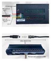
5. As mentioned above the cable is too short.
6. The On button is separate rather than being part of the Display.