diy solar

diy solar

JK 4S 200A BMS

Does the app support multiple devices, or once you connect one phone it can't connect to another? I'm running the latest v4.7.1
I connected my old phone first since I wanted to do some testing and have that always connected, it's an Android 10, and it worked flawlessly.
I now tried my newer Android 12 phone and it's not finding the BMS on the scan page.

Also, I realized my control page is different, I have a change password at the top and an emergency switch at the bottom but no shutdown or factory reset buttons. Is this a change in the new version?
 
Does the app support multiple devices,

Yes - you can switch between them in the top left menu.

I now tried my newer Android 12 phone and it's not finding the BMS on the scan page.

Make sure you enable location privileges; recent Android versions require that when an app needs Bluetooth.
 
Yes - you can switch between them in the top left menu.


Make sure you enable location privileges; recent Android versions require that when an app needs Bluetooth.

I did allow location, but apparently, it also needed nearby devices' permission. Works now.

Still don't know why I don't have shutdown or factory reset buttons, but I'm probably never going to use them so that's fine.
 
... A "Would be Very Nice" addition would be to be able to Clear Activity Log, especially handy for testing/debugging a pack.
Also, if a BMS is named, it would be good to display that name in the title bar, because when multiple BMS are in use this can become somewhat confusing.

Have Fun.
Thanks for posting pics from your your s earlier version. Although my draft documentation (from the end of April) shows your "Control" page, My "Control" page (V4.7.1) has 5 entries.

The first is added, being a slightly redundant "modify" button to change the "settings" password, the last being the the last being the new "emergency" switch to enable discharge for a short period (in spite of any under-voltage, over-temp, or other discharge-disabling error condition being detected and not yet recovered).

The "Factory Restore" is removed, its function is performed within "settings" by choosing or re-choosing a battery type. That overrides your custom parameters with their factory defaults (including your count of cells for the battery pack, and your corrected low-temerature charge limit for the case of LFP battery cells - the default allowing for catastrophic charging at below-freezing temperatures in the case of LiFePO4 cells).

IIRC, the rest of "battery type" does not go through any kind of "Are you Sure?" conirmation, and it might be desirable to add such a query before overwriting user-entered parameters.

The "Shutdown Board" item is also removed. Although shutdown may still occur according to an undocumented and non-settable "maximum idle time" parameter hidden within the BMS microcde, I can only perform a forced shutdown via the plug-in the physical power button, or the GUI status board which plugs into the same port.
- - -
The Board Name seems to be readily accessible from all 3 panels//pages, using the upper left "hamburger" and then (on Android, at least) using the system back arrow (bottom of the screen) to return to the panel where you invoked the hamburger. The hamburger shows the original scanning/connecting page, but with the currently connected BMS marked with a tilted pencil (to the right of its name).
- - -
Using the system back arrow to return to the previous panel doesn't establish a new session, BMS and App remains connected through the process. The menu bar center is currently filled with the actively incrementing "run time" of the BMS since last restart, and likely doesn't contain enough unused horizontal space room to add a long device name as well. I would not like to see this changed.
- - -
The stack of 50 error messages is contained in a FIFO buffer, losing the oldest error message #50 from the bottom of the list whenever a new error message is posted to the top. This has the possible side effect of losing information with regard to the "primary cause" of an error situation which leads to many follow-up warning messages, but "file management" of multiple lists would be a complex addition - and they can't be downloaded anyway. I recommend no change.
 
The "Factory Restore" is removed, its function is performed within "settings" by choosing or re-choosing a battery type. That overrides your custom parameters with their factory defaults (including your count of cells for the battery pack, and your corrected low-temerature charge limit for the case of LFP battery cells - the default allowing for catastrophic charging at below-freezing temperatures in the case of LiFePO4 cells).
Tried that 2 days ago, even changed battery type & then back and same ol.
Screens shown are from the NEEY edition, not mine.

I am now using 4.7.1 Android Version.

PS: Just went out and tried, charge/discharge turned off, then switched to Li-Ion, the LTO and back to LFP. The setting I had input returned, so No not a Reset to Default Values as the settings are stored and recovered.
 
Last edited:
Tried that 2 days ago, even changed battery type & then back and same ol.
Screens shown are from the NEEY edition, not mine.

I am now using 4.7.1 Android Version.

PS: Just went out and tried, charge/discharge turned off, then switched to Li-Ion, the LTO and back to LFP. The setting I had input returned, so No not a Reset to Default Values as the settings are stored and recovered.
I just "reset' to LiFePO4 without actually changing battery type at all. Some settings were retained but the critical configuration parameter "Cell Count: was reset to 8 (I have only 4 cells in this battery pack). Continuous Charge Current was reset to only 25A, my much shorter Charge OCP Delay was set back to 30 seconds, my much shorter Discharger OCP Delay was reset to 300 seconds (far too long), and critical parameters Charge UTP and Charger UTPR were set back to default values far below freezing, allowing LFP cell destruction in under-freezing temperatures. Trivial parameters such as "Power Off Volume" were also lost and reset to default values.

I can't explain your different experience. my Android 4.7.1 is not saving previous parameter values when overwriting most of them with defaults.

Now changing my overwritten parameters back to "good" values. :eek:
 
Last edited:
I can't explain your different experience. my Android 4.7.1 is not saving previous parameter values when overwriting most of them with defaults.
Maybe because I am using B2A24S15P BMS' ? I dunno, I've manually reset them all to what I want and they are humming along quite nicely for now. More changes & additions to go... so time will tell (not too long) Thank Goodness.
 
I would put a 150A Class T fuse on each pack if you often go to 120A. If you stay below that all the time with each pack (including when one or two packs are out of service), use 100A.
I usually pick my class T fuses slightly higher than the maximum current each pack will see, within the max limits of the BMS.
By max limits of the BMS you mean the continuous discharge of 200A or max of 350A?

By having it lower than 200A means the BMS is also protected by the fuse right?

The max current my system will receive based on my audit is 110A, I want to size a big higher accounting for future upgrades, but less than 200A is probably enough. Victron recommends a 250A fuse for the 24/3000VA though, which is a lot higher considering it outputs max 2400W.
Victron is recommending that figure to allow for the maximum instantaneous draw from the Victron and that would be a good limit to use (although the BMS can be a bit higher). I would not go any bigger than 300A in your situation, and 250 would be another smart choice: Anything higher than 250A implies an unwanted short circuit.
 
Last edited:
Also remember the higher the amperage rating of the T fuse the slower it is for a given overcurrent. i.e. a 150A JLLN T fuse subjected to 500A will blow at 0.2s while a 300A T fuse will take over 1000s. A short on a LiFePO4 is likely to deliver a lot more than 500A so may not be relevant but interesting to know none-the-less. There is also different versions of T fuses as someone else mentioned with different characteristics. A JLLN Littlefuse T fuse blows a lot faster then a JLLS T fuse.
 
Also remember the higher the amperage rating of the T fuse the slower it is for a given overcurrent. i.e. a 150A JLLN T fuse subjected to 500A will blow at 0.2s while a 300A T fuse will take over 1000s. A short on a LiFePO4 is likely to deliver a lot more than 500A so may not be relevant but interesting to know none-the-less. There is also different versions of T fuses as someone else mentioned with different characteristics. A JLLN Littlefuse T fuse blows a lot faster then a JLLS T fuse.
Interesting, I didn't know that but makes sense. Yeah, I started researching T fuses and found there are many different kinds, not just the blue seas everyone talks about. I've just posted here: https://diysolarforum.com/threads/class-t-details-and-specs.35899/post-529321 some examples I found sold by a distributor here in Italy and most of Europe.
 
By max limits of the BMS you mean the continuous discharge of 200A or max of 350A?

By having it lower than 200A means the BMS is also protected by the fuse right?

200A, or even less if you never get to 200A in normal operation. This indeed helps protect the BMS.

And as others have pointed out: you really want to check the curve of your particular class T fuse to see how long it takes to interrupt which current...
 
my understanding is that on the JK BMS, the sense wires do not need to be the same length. Is this correct or a myth?

I believe that on other BMS's the sense wires need to be the same length but that the JK BMS will calculate the resistance of the wires when it does its active balance thing and enter that actual value into the unit to compensate.

Can anyone familiar with the JK BMS verify this or provide the actual way that the sense wire resistance it figured on the JK? The screen shot is of the JK app printout that I pulled from the forum. This user told me that the wires had been cut to fit the distance to each cell.

Hopefully my 4s JK will arrive tomorrow. It has been lost in my local USPS for the last two days so I am nervous but hopeful.
 

Attachments

  • jk resistance.png
    jk resistance.png
    146.8 KB · Views: 2
my understanding is that on the JK BMS, the sense wires do not need to be the same length. Is this correct or a myth?

I believe that on other BMS's the sense wires need to be the same length but that the JK BMS will calculate the resistance of the wires when it does its active balance thing and enter that actual value into the unit to compensate.

Can anyone familiar with the JK BMS verify this or provide the actual way that the sense wire resistance it figured on the JK? The screen shot is of the JK app printout that I pulled from the forum. This user told me that the wires had been cut to fit the distance to each cell.

Hopefully my 4s JK will arrive tomorrow. It has been lost in my local USPS for the last two days so I am nervous but hopeful.
Equal length Sense Wires is essential, different lengths will affect the resistance readings which are essential for diagnostics & troubleshooting. You can shorten them but ALL of them to keep consistency. Also when you attach Ring Terminals be sure to do a Resistance Test with your DVOM to ensure they are all good and equal, if not a bad crimp/solder joint (if you choose to solder) could & would cause messed up readings. They are MilliOhm Sensitive.
 
my understanding is that on the JK BMS, the sense wires do not need to be the same length. Is this correct or a myth?

I believe that on other BMS's the sense wires need to be the same length but that the JK BMS will calculate the resistance of the wires when it does its active balance thing and enter that actual value into the unit to compensate.

Can anyone familiar with the JK BMS verify this or provide the actual way that the sense wire resistance it figured on the JK? The screen shot is of the JK app printout that I pulled from the forum. This user told me that the wires had been cut to fit the distance to each cell.

Hopefully my 4s JK will arrive tomorrow. It has been lost in my local USPS for the last two days so I am nervous but hopeful.
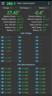
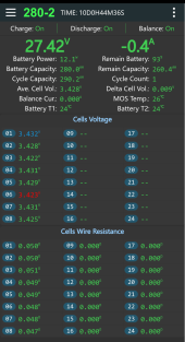
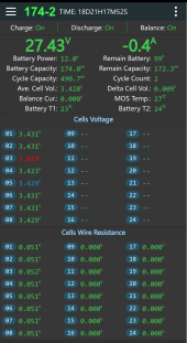
JK does present a resistance figure for each balancing lead, on the status screen (as shown in your png).

As a new test, I loosened the terminal on cell 3 and tried holding that BMS balancing lead against the bus bar with less force, using only the edge of the ring terminal. I did see voltage drop on the pack, but it ultimately responded by shutting down with an error about the cell count (determined to be only 2, with my loosely held terminal being treated as a non-connection. This was a non-recoverable situation, except via proper reconnection (with ~65 inch-pounds on the terminal nut, and the ring terminal correctly set underneath that nut.)

Before and following recovery, the figures for my "4S" test pack with shortened BMS leads are smaller than shown in your PNG. I don't remember the figures from before the test. Following re-assembly and compression of the 3rd cell "+" terminal, it now shows .031 for cells 1, 2 and 4, while showing .030 for cell 3. These are constant values, never changing.

The voltages shown on the BMS 'status' page for my 4S test pack tend to bounce around a bit,,typically varying by 0.002 Volts from one measurement to another, usually with a "higher voltage" shown on either cell #3 or cell #4. The reporting rate to the cellphone App (Android) seems to be about 3x per second. My coulomb counter voltages readings do not exhibit those "bounces".

In setting up 6 in-use BMS leads for my own 4S "tester" pack, I cut all 10 of the supplied leads to about 1/2 of their original length, before crimping terminal rings onto the 6 leads actually used. You can apparently modify the 'status-shown' resistance values by tuning resistance for individual leads within the parameter 'settings' panel, if you have an extremely accurate tool for measuring that resistance. But I felt no need to try doing that.
- - -
I have no idea when or how the BMS attempts to find a "Cell Wire Resistance" value. It may happen only at startup, with no schedule of repeated re-testing. But, my lower figures (0.030 and 0.031 ohms) seem to imply that a measurement has been taken on my shorter and less resistive wires.
 
Last edited:
JK does present a resistance figure for each balancing lead, on the status screen (as shown in your png).

As a new test, I loosened the terminal on cell 3 and tried holding that BMS balancing lead against the bus bar with less force, using only the edge of the ring terminal. I did see voltage drop on the pack, but it ultimately responded by shutting down with an error about the cell count (determined to be only 2, with my loosely held terminal being treated as a non-connection. This was a non-recoverable situation, except via proper reconnection (with ~65 inch-pounds on the terminal nut, and the ring terminal correctly set underneath that nut.)...
Given the tiny amount of resistance we are talking about, I would assume that the pressure method you outlined above would produce huge swings that would not be within the ability to adjust to. You could try making a jumper lead with one of the cut off pieces with ring terminals on both ends and then connect it between one lead and the cell it is monitoring.
The resistance values on the screen shot I provided above were all generated by the JK without input from the user.
 
Equal length Sense Wires is essential, different lengths will affect the resistance readings which are essential for diagnostics & troubleshooting.
I'd like verification of this since I used some butt splices to add length to wire so they are not equal. I thought that is why it has resistance calculation listed for each wire so it can take any deviations into account.
 
I'd like verification of this since I used some butt splices to add length to wire so they are not equal. I thought that is why it has resistance calculation listed for each wire so it can take any deviations into account.
Did your wire resistances change in a rational fashion for the lengthened wires? I would like that you should see more resistance on that wire.
 
I'd like verification of this since I used some butt splices to add length to wire so they are not equal. I thought that is why it has resistance calculation listed for each wire so it can take any deviations into account.
Seriously ?
Now that I have switched "every" pack to all identical JKBMS, and normalized all the busbars on all packs, even right down to using identical screws on the cells etc... it's awful plain & simple to see.

When Running the Chargery BMS, 1st install iteration used the standard Harness from chargery, but with various busbars it clearly showed a broad range of resistance per cell, largely due to the different busbars and there was a significant difference with the harnesses that were shortened & this with = Length sense wires. 2nd Iteration of Chargery Install, used = Length Harness to a QNBBM Active Balancer which then used heavier wire to go the cells and that again had different Resistance Readings. The resistance was also tested with a DVOM and a YR1035+. With the 2 Different Setups, the Busbars varied either in thickness or width (110 Pure Copper Stock) and one test pack also used double vendor supplied busbars and that was also different than the rest.

Now that everything is equalized / normalized to be Uniform, including the BMS & Version of same, it is extremely clear how uniformity is a key thing to establish in order to compare, troubleshoot etc... In fact it really simplified getting all the cells leveled up and ensuring a very decent comparison between multiple packs in a bank.

Going back to the Original ShunBin Pack Disaster, I replaced it defective BMS with a Chargery. That pack had 16 cells for a 24V Pack I had to extend some of the harness to get to the end of the "Long Block" and teh extended wires (soldered butt joints) were significantly different and troublesome with the cells, at which I ripped all that apart and turned the 16 cells into 2 packs of Simple 8S Config which made a huge difference.

Over the past few years with various tests, tweaks and adjustments and even minor to major configuration changes have proven that KISS Keep It Sweet & Simple bears 100% True. I'm sure I can find White Papers and Other tests, but I do NOT Do that anymore because then everyone argues that material even when they bother to read to material.

That is the Only Answer you will get from me on that point. Accept the extended experience use your Critical Thinking and choose whether you accept it or not. Argue it, debate, alt-reality it, I don't care. You have the Freedom of Choice to make your own decisions but that also makes you responsible for those choices, regardless of the outcome, good, bad or neutral.

PS, I'm just a shmuck who wrote / rewrote BMS Manuals, Instructions & Docs, as well as Battery Assembly guides, some of which have resource links to the specific bits related... But What do I KNOW ?
 
Last edited:
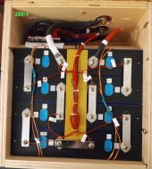
280-1 Final Config, June-2022. All Packs are Identical. (What a Rats Nest of Sense Leads eh)
* Red 4AWG Silicone IS NEGATIVE (they ran out of Blue and sent that instead)
280-1 (Final 06-2022).jpg

3 Packs from the Bank (In float mode packs balancing out, cells are self-explanatory)
1655578817023.png280-2 Final (06-2022) BMS Screen.png174-2 Final (06-2022) BMS Screen.png
 
Back
Top