diy solar

diy solar

JK 4S 200A BMS

I will be more than happy if you can provide shunt that has ability to measure 200+ A and it is capable to measure very small current draw. You have probably misunderstood my post. I was not referring to the JK bms issue but your overall expectations that you should expect from JK BMS . And especially if you looking on the shunt that can have tolerance to less than 1% +/- SOC. None of Chinese BMS have sophisticated algorithms specifically designed for one type of chemistry that take in account all variables to present true SOC. Cells drifting when not used and unknown batch of cells in pack are biggest unknown. So my apologies if I did make you feel bad.
I never feel bad in good conversations, you've been great! :giggle: In general though, the JK BMS should not be presenting '0% left!' when the well-matched cells (known by a JK setting to be LiFePO4) have been designated as '230Ah', and the downward drift occurs with no external discharge at all (from an even higher SOC when taken from the test bench). When removed from the test bench and first taken to the RV trailer for wire-up and testing of high RV loads, when JK showed only 6% left. The genuine remaining capacity at that moment was over 97% - and when cell voltages are that high, the SOC versus Voltage curve has fairly high slope, allowing Voltage alone top provide a good SOC figure for rested LFP cells. In initial top balance, testing down to 12v and calculating the remainder, 3 of 4 cells exceeded 230Ah, and the "weak" came in at 229.

Even before doing any discharge work at all, the JK App was showing "6% left" in the pack - sitting on the test bench at a high SOC. The only value my further discharging the battery pack in Trailer testing (down to around 70%) WRT this issue was the confirmation that JK (thank goodness) does not use a ZERO value to shut down discharge of the battery pack. It at least allowed the pack to continue supplying discharge current. But the defect is present and profound - if the new JK (and its cellphone App) can't be fixed to show SOC with moderately decent accuracy in the App, I recommend that the figures should NOT be shown by the App at all.
 
@rickst29
I agree with you. But there is so much we can get with generic BMS that at times of design was probably never intended for high Ah cells. Dedicated shunt especially in multi parallel setup should be more accurate. I usually look at lifepo4 voltage curve....if going down from flat part it is around 10% SOC or less....if it is in flat curve it will be anywhere between 20-80% SOC depending on saturation and time it was not used. I do usually account 1% losses ? if left for 30 days. Temperature matters also but most of my projects are usually in sweet temperatures spot.
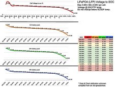
That's what I'm doing, with separate shunts per pack. But if you look at the voltage curve for idle LFP cells, you can note that the "flat part" isn't completely flat, and you may therefore also use the smaller differences in cell voltage (from 3.325 @ 80% SOC down to about 3.200 @ 20% SOC) to estimate SOC on idle packs. Conversion from Voltage to SOC via the attached chart has been pretty reliable.

With high quality voltage measures from the Coulomb Counters/Shunts, on idle packs which have rested for a while, I've confirmed the chart to be pretty close within a sequence of "top balanced, measured on the way down, and measured again on the way back up)" values of voltage versus AH in my own packs, at near STC conditions. (The per-cell chart shows a erroneous drop-off near 100% SOC, which isn't really there - it may have been caused by 'balancing' creating interference with the measurement of a BMS-managed cell or pack.)

In my Travel Trailer, I keep the lower-right chart, rather than the full graph. I pulled this chart from somewhere on the Net, and don't remember its source. It might already be present on this forum.
 

Attachments

  • LFP-Voltage-Chart.jpg
    LFP-Voltage-Chart.jpg
    481.1 KB · Views: 26
@rickst29 what Ah ratings are for this charts?
The chart is applicable to any cell size. (The characteristics are a nature of the chemistry, not the cell size). But, from one type of cell to another, the length of time that "surface effects" from charge or discharge must be allowed to "settle in" probably varies: That would be related to volume of the cells, and the cathode / anode terminal designs.
 
The chart is applicable to any cell size. (The characteristics are a nature of the chemistry, not the cell size). But, from one type of cell to another, the length of time that "surface effects" from charge or discharge must be allowed to "settle in" probably varies: That would be related to volume of the cells, and the cathode / anode terminal designs.
You are correct....i was looking at my data logs at various different Ah cells....only differences is dropping from flat curve little different on less than 100 Ah cells.
I have downloaded your chart and printed out it will be seating on my wall in the shop. Appreciate all the time to invest in this to make this chart.
 
@rickst29
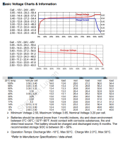
SOURCE one of my resources I posted a while back

Also from another of my resources which DZL posted, this is an extract from from there. Heaps more info in there.

Luyuan Tech Basic Lifepo4 Guide V1.0A​

BTW: This is included within Luyuan Tech Cell Packages as a printed glossy.
1656351664344.png
 
Last edited:
On the JK app, can someone what the values of Cycle Capacity" and "Remain Capacity" mean and what they should tell me?
I thought that they told you how many amps had been used and how many amps remained until empty but now am questioning that. I have seen some screen shots where if you add those two numbers together, they do not equal "Battery Capacity"
 
Remaining Capacity is gen both as AH and as a percentage of the battery pack. My "Cycle Capacity" is currently reported at 186.7Ah, while my total capacity (now "recovered" and pretty much correct) reports 225.4Ah and 98%. There seem to be a reservation of about 19% in the difference.

I assume that "Cycle Count" will be incremented if you ever push "cycle capacity" past zero - but I'm not sure how it works, because my total capacity has gone down to 0% without JK reporting a "Cycle" to have occurred (via incrementing "Cycle Count").

There may be some "training" and tuning process going on within all of these numbers: JK may slowly "training itself" during the first few major discharge and recharge cycles.
 
my understanding is that on the JK BMS, the sense wires do not need to be the same length. Is this correct or a myth?

I believe that on other BMS's the sense wires need to be the same length but that the JK BMS will calculate the resistance of the wires when it does its active balance thing and enter that actual value into the unit to compensate.

Can anyone familiar with the JK BMS verify this or provide the actual way that the sense wire resistance it figured on the JK? The screen shot is of the JK app printout that I pulled from the forum. This user told me that the wires had been cut to fit the distance to each cell.

Hopefully my 4s JK will arrive tomorrow. It has been lost in my local USPS for the last two days so I am nervous but hopeful.

I purchased B2A24S15P BMS after watching this video and set it up and 8 cell 280ah and it ran for several weeks ok no issues. I then built a better battery shelf and disconnected completely and setup on shelf. The same cells were not in the exact same position but didn't think it mattered but now I have a 'Wire resistance too large' message coming up and it won't balance! :( I have gone over all connections and tightened screws etc but still same. I thought maybe if I did a factory reset to wipe all data of it like it was when new it might work. How do you actually do a factory reset? Looked everywhere - no answer as yet. Why is this resistance message coming up?
 
Sadly "Reset to Factory" did not make it back to the app "yet", don't know if it will.
Just go into Config & Disable Charge, Discharge & Balance. Then go to Settings, select another battery type and wait a sec, then reselect LifePo which will reset "SOME" things but not all.
There are some default settings issues IE Hi & Lo Temp protection for one, the numbers are NOT for LFP, and some other details.
Have a Look at this thread, it should enlighten and help you setup with a more appropriate setting for LFP.
Also make sure the Sense Leads are on the + side of each busbar, before fustsing with it, disconnect the B+ first to shut off the BMS manually.


1656574159723.pngPer Manufacturer Specs

Hope it Helps, Good Luck
 
I contacted Hankzor and they said: "Thank you for your information. We are evaluating the cause of this problem. We will update the app as soon as possible to reply to this bug. thank you."

I told them there needs to be a factory reset to clear all settings. They are apparently going to sort out on monday with hopefully a new app update. :)
 
Heat Function interface

(Only BMs equipped with heating function can use heating interface)
Description of heating function:
Battery temperature is below low temperature charge protection, turn off charging, turn on heating.
Battery temperature is higher than low temperature charge recovery temperature, turn on charging, turn off heating.
Cryogenic charge protection is a parameter that can be set within APP


The heating power depends on the battery voltage and the resistance value of the heating film.
Battery voltage U.
Heating resistance R.
Power equals U*U/R
Heating current I=U/R;
The maximum I (current) of the board design is 3A


MAX heating Power 200W (100W of B2A8S20P)
This condition must be met.
@Nami
sorry for the blast.
but I don‘t understand this words

Die grün 5PIN kabel der heizung kabel muss verbunden werden die heizung pad,
Und der rest der schwarz und rot kabel sind verbunden die smart ladegerät
(Nach die smart ladegerät links die BMS,
Es erkennt die temperatur der batterie durch die BMS,
Die automatisch überwacht die lade status der batterie)


this are my language but I don’t know how I connect one heating pad.
is it possible to get one outline of the wiring Pls.

regards and thx
 
My new JK-B2A8S20P-H sometimes crashes randomly when the Android app is opened.
2P4S configuration of 200Ah LIFePo4 cells.
So far:
- Ran perfectly when installed, app was frequently opened and viewed
- Opened the app 3 days after the install and the BMS crashed, shutting down the battery. Stuck in a reset loop and won’t respond to the on/off button. Disconnecting and reconnecting the balance leads just restarts the loop.
- Uninstalled the 4.7.1 app and updated to 4.7.3. No change
- Found 4.7.4 and updated to that. No change

Sometimes the app would open and I could get a screen shot before it became inaccessible.
- Sometimes all seemed normal
- Sometimes I’d see Cell Count is Not Equal to Settings, all the cell voltages blank

Saw Nami’s note about max balance cable length of 1.3m. My leads had need extended due to the battery configuration and were of unequal length with a max of 1.4m. Cell wire resistance was within .009 ohms. Remade all the balance leads to 1.25m and equal length (to be sure). Cell wire resistance was now within .001 ohms.
- BMS restarted and ran happily for two weeks, frequent app views.

Today I opened the app and the BMS crashed, shutting down the battery with the behaviour as the first time.
- Updated the app to 4.7.6
- Upon first opening the app, the BMS restarted but with the error message “Warning Equil. Res. too large” and all the cell wire resistances were blank, then the BMS went back into the restart loop.

Any suggestions on how to resolve this?
 
Unfortunately the HankzorBMS store has advised some chips need replacing?? After repeated requests they keep stalling and blaming their supplies and still won't provide a solution and replace. I am very disappointed so far with the service especially after spending nearly $500 on 2 BMS's and being left in the lerch.
 
Unfortunately the HankzorBMS store has advised some chips need replacing?? After repeated requests they keep stalling and blaming their supplies and still won't provide a solution and replace. I am very disappointed so far with the service especially after spending nearly $500 on 2 BMS's and being left in the lerch.
Same. My 4s was packaged in a very flimsy and way too big a cardboard box with just a single layer of thin bubble wrap. It was so poorly packed that it rattled around inside of the box. The heat-sink plates were bent with one mounting ear bent 170º. I asked for a replacement, they refunded 30% instead.
 
First the Grade B cell drama, now BMS supplier drama.
What is next: Solar Panel drama too? Oh yeah we have that too when supplier refuses to replace broken ones.

All these renewable energy DIY projects are becoming a huge pain.
 
the Samlex products are a good value and provide features not found in the other two.

What features do you see that Samle has that the other 2 do not have? I am interested in 48v and Samlex are a bit sparse at that voltage. the highest rated Inverter is only 2800w and I dont see anything about being able to parallel the 48 v inverter with another. 2800w is a bit limiting.
 
Back
Top