diy solar

diy solar

JK 4S 200A BMS

I'm also going to try the JDM route which I will have the JK incoming but I need two BMS's anyways so guess I will try both. I think the one think I was liking on the JK was option for the screen. I like having this for my systems are portable ish and having that display on the outside helps with the stats.
The JBD does have a screen option as well (at least some of their models do).
Has optional BT, Screen (UART or rs485 versions available) and Rs485 module.

BUT I don't think you can use them all. lol
In my case I don't think I can use the screen. As I will use the BT (which connects to UART port), and the rs485 port going to Victron VenusOS (CerboGX, Venus or Rasp Pi). LCD screen is available for the UART port or the rs485 port (different screen for different port).

JIABAIDA-Accessories-Bluetooth-Module-UART-RS485-LCD-Displayer-For-Lithium-Battery-Smart-BMS-3S-20S-With.jpg_Q90.jpg_.webp
 
Last edited:
I still have not heard from them !!

I have been experimenting over the last month and have found that using a normal JBD bms and hooking up a Heltec 5A active balancer is not only cheaper but works soooo much better than JK !! I had a pack with a JK and it would never ever actually balance or get close but after installing the Heltec and giving it a few days the pack is now balanced and stays balanced ! The JK could not even come close to it in performance!!

I have give up on JK BMS's they are not worth the trouble! I know they sound like they should be good but when you put them to the real test they can't pull their weight anyway let alone the BACKUP SERVICE that DOESN'T EXIST! when they fail!

@Alltron I am planning a similar setup with JBD and the Heltec and was hoping to pick you brain.
But I posted in a more related thread as to not hijack this one and possible help others by making it easy to find and comment on.
If/when you get a moment if you can take a peak as I am interested in your testing and settings.

https://diysolarforum.com/threads/active-balancer-ok-to-use-with-bms.46573/

Thank you!
 
I was just getting ready to order two of the B2A8S20P from Hankzor store. They were in my cart ready to go, decided to do some reading first and found these threads. Between this one and a few others with a buzzing sound on the inverters time to sit back and see how things go. Guess I will start looking into the JBD 4s 200a BMS-SP04S034 for the time being.
 
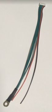
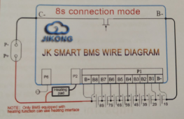
The 5-wire "main cord" is shown as a switched grounding connection in Nami's previous diagrams.

If heating pad current will be below 3A, and total power also below the limit on an 8S "25.8V" battery pack, the heating pad "ground" can be wired directly to the bundled 'main cord' of green wires. The black and red wires ARE NOT currently used at all: They are only present on the connector for a possible future power supply, to be designed JK. The heating pad "hot" connection, and any heating pad switch, should be left enabled at all times. The JK will enable the "main cord" grounding connection whenever the detected battery pack temperature has fallen below the 'minimum charging voltage' temperature setting of the BMS.
In my upcoming test configuration, using a single 4S battery of adequate size, I will be testing two ways. First, with a single "12v" heater pad connected directly from the +12v bus to this grounding cord. That test will run at slightly over 2A.

Then I will re-wire, using this switched grounding connection as the "coil" ground of a normally off (NO) automotive-type mechanical Relay. This Relay will have a "12V" coil (matching my 4S battery pack), although automotive-type Relays with "24V" coil voltage are readily available as well. An 8S "24v" battery pack would use one of those instead. In this configuration, the Relay "Load" terminals interrupt the permanently connected "hot" wire, which is driving two parallel heating pads @ 2A each, 4A total current. (The pads are permanently connected to the main grounding bus, outside of the BMS.) Use of the Relay supports higher current to the pads, through the Relay's "load" terminals, while using hardly any current at all to activate the coil. In my production configuration, I will have 3 heater pads.

Will your heater pad consume more than 3A? And, was this "verbal diagram" sufficient for you?
For me a picture is worth a 1000 words.... was one ever produced (to connect a heating pad)
 
For me a picture is worth a 1000 words.... was one ever produced (to connect a heating pad)
Hi. I'm happy to add more words, but a photo of my setup would be impossible to understand (including dozens of irrelevant wires doing other things). My THREE heater pads run around 2.4A each (varying according to supply voltage). With just one of those heater pads, the pad "-" could connect directly to the JK multi-wire heater interface cord, with "+" permanently connected to the "12v" bus (or optionally connected through a switch as well).

In my own "12v" case the current through all 3 pads is too much for the JK interface (about 70W maximum at high voltage, it's also limited to 3.0 Amps as an absolute maximum current value). Only the the coil "-" is connected to the JK interface. (This is the automotive coil, "Bosch" type also sometimes listed as 'JL9214', I left the 5th pin unconnected.) The RELAY COIL draws only a tiny bit of current through the JK interface when JK-BMS enables that ground connection internally. "Coil +" is connected the 12v supply, in my case through a separate enabling switch (a very small one).

On the Relay switched power circuit connections, one side gets +12v from the main power bus (in my own case, with multiple batteries attached). the other side goes through a 4-way connector to reach the 3 "+" power terminals on the heater pads. (A wiring nut is adequate, although I nvere use those for so many wires within my vibrating travel trailer.)

From a later message in the Thread, you will see that the BMS passed the "single heater pad" test with no issues at all (A+). Following subsequent instllation into my travel trailer, the JK-BMS has also controlled the Relay circuit (and all 3 heater pads) PERFECTLY in a chiller induced test. That resulted in about 100 watts of total power through the heater pads.
 
Last edited:
Hi. I'm happy to add more words, but a photo of my setup would be impossible to understand (including dozens of irrelevant wires doing other things). My THREE heater pads run around 2.4A each (varying according to supply voltage). With just one of those heater pads, the pad "-" could connect directly to the JK multi-wire heater interface cord, with "+" permanently connected to the "12v" bus (or optionally connected through a switch as well).

In my own "12v" case the current through all 3 pads is too much for the JK interface (about 70W maximum at high voltage, it's also limited to 3.0 Amps as an absolute maximum current value). Only the the coil "-" is connected to the JK interface. (This is the automotive coil, "Bosch" type also sometimes listed as 'JL9214', I left the 5th pin unconnected.) The RELAY COIL draws only a tiny bit of current through the JK interface when JK-BMS enables that ground connection internally. "Coil +" is connected the 12v supply, in my case through a separate enabling switch (a very small one).

On the Relay switched power circuit connections, one side gets +12v from the main power bus (in my own case, with multiple batteries attached). the other side goes through a 4-way connector to reach the 3 "+" power terminals on the heater pads. (A wiring nut is adequate, although I nvere use those for so many wires within my vibrating travel trailer.)

From a later message in the Thread, you will see that the BMS passed the "single heater pad" test with no issues at all (A+). Following subsequent instllation into my travel trailer, the JK-BMS has also controlled the Relay circuit (and all 3 heater pads) PERFECTLY in a chiller induced test. That resulted in about 100 watts of total power through the heater pads.
Do you absolutely need a relay or you can wire the heater pad (that has the right amperage and voltage ratting) DIRECTLY to the JK without a relay? I think I am reading that I do not need one
 
Last edited:
Do you absolutely need a relay or you can wire the heater pad (that has the right amperage and voltage ratting) DIRECTLY to the JK without a relay? I think I am reading that I do not need one
If less than 3A (AND total watts below 70w in the case of a high-voltage heater connection with low amperage), you can connect direct. That test passed with flying colors.
 
If less than 3A (AND total watts below 70w in the case of a high-voltage heater connection with low amperage), you can connect direct. That test passed with flying colors.

3A is not enough, should be upped to 10A.
Bah! I think it is more than enough. If your battery is in an isolated environment (insulated box)... that is more than enough to keep it over freezing using very little power. My opinion and real life experience
 
My heating system uses a bit over 1A and keeps my 8S 230Ah battery between 50°F and 60°F when the ambient temperature is below freezing. Oh, and it only stays on for about 3-4 hours per 24 hour day.
Agreed... that is what I am seing also.... about 100 watts of heating per day
 
The JBD does have a screen option as well (at least some of their models do).
Has optional BT, Screen (UART or rs485 versions available) and Rs485 module.

BUT I don't think you can't use them all. lol
In my case I don't think I can use the screen. As I will use the BT (which connects to UART port), and the rs485 port going to Victron VenusOS (CerboGX, Venus or Rasp Pi). LCD screen is available for the UART port or the rs485 port (different screen for different port).

JIABAIDA-Accessories-Bluetooth-Module-UART-RS485-LCD-Displayer-For-Lithium-Battery-Smart-BMS-3S-20S-With.jpg_Q90.jpg_.webp
I could not get the RS485 display to work
I think i got a unit that was mislabeled.
I put a scope on data lines and looks like RS232
2.5v swing
 
Hi. I'm happy to add more words, but a photo of my setup would be impossible to understand (including dozens of irrelevant wires doing other things). My THREE heater pads run around 2.4A each (varying according to supply voltage). With just one of those heater pads, the pad "-" could connect directly to the JK multi-wire heater interface cord, with "+" permanently connected to the "12v" bus (or optionally connected through a switch as well).

In my own "12v" case the current through all 3 pads is too much for the JK interface (about 70W maximum at high voltage, it's also limited to 3.0 Amps as an absolute maximum current value). Only the the coil "-" is connected to the JK interface. (This is the automotive coil, "Bosch" type also sometimes listed as 'JL9214', I left the 5th pin unconnected.) The RELAY COIL draws only a tiny bit of current through the JK interface when JK-BMS enables that ground connection internally. "Coil +" is connected the 12v supply, in my case through a separate enabling switch (a very small one).

On the Relay switched power circuit connections, one side gets +12v from the main power bus (in my own case, with multiple batteries attached). the other side goes through a 4-way connector to reach the 3 "+" power terminals on the heater pads. (A wiring nut is adequate, although I nvere use those for so many wires within my vibrating travel trailer.)

From a later message in the Thread, you will see that the BMS passed the "single heater pad" test with no issues at all (A+). Following subsequent instllation into my travel trailer, the JK-BMS has also controlled the Relay circuit (and all 3 heater pads) PERFECTLY in a chiller induced test. That resulted in about 100 watts of total power through the heater pads.

I remember your tests, and I understand quite clearly your description, as I have used this arrangement for other purposes in the past, but... I'm not understanding JK's instructions on the heating pad! :(

I've just received a brand new JK-B2A8S20P-H

AliExpress instructions:

1667256641506.png

Provided cable
1667256717113.png


Provided Instructions

1667256768043.png


Would you please help me making some sense out of this?
I don't think @Steve_S has this model in his powerhouse... right? :unsure:

Thanks in advance!
 
The individual red and black wires do not serve a purpose in heating use, and should not be stripped or connected to anything at this time. They may be usable with an un-released "smart charger" product in the future. Connect only the green bundle (as "ground for the heater pad, or "coil -" for a switching power relay).

The picture is good, with you taking note that the "heavy black" connection P2 to the heating pad is the green bundle of the interface cord.
 
Last edited:
I remember your tests, and I understand quite clearly your description, as I have used this arrangement for other purposes in the past, but... I'm not understanding JK's instructions on the heating pad! :(

I've just received a brand new JK-B2A8S20P-H

AliExpress instructions:
..
Provided cable
..
Provided Instructions
..
Would you please help me making some sense out of this?
I don't think @Steve_S has this model in his powerhouse... right? :unsure:

Thanks in advance!
I do not use the Heater Capable Models, my Powerhouse is heated to 50F as it also contains my 50 gallon water pressure tank and well head on the other half of the building.
 
The individual red and black wires do not serve a purpose in heating use, and should not be stripped or connected to anything at this time. They may be usable with an un-released "smart charger" product in the future. Connect only the green bundle (as "ground for the heater pad, or "coil -" for a switching power relay).

The picture is good, with you taking note that the "heavy black" connection P2 to the heating pad is the green bundle of the interface cord.
Thanks a lot!!
Totally understood!
It's incredible how included instructions don't pair up with the product , not even the marketing material... it's only good people like you and the ones in the forum that make all this work.
Again, thanks!
 
I am uncertain whether the output CURRENT and POWER limits (which have already been documented for this interface interface), can be protected from an over-current configuration by the BMS itself. To create such a test (for slightly more than 3.0A), I can a 2nd resistor in parallel with this heater pad. I will await confirmation from Nami (regarding the presence "3A" over-current protection within the BMS itself) before doing that.
Have you meanwhile received confirmation from Nami or otherwise regarding the presence of "3A" over-current protection within the BMS itself).
Knowing this reliably would be very helpful for me, as I am just about to build such a system.
 
Back
Top