diy solar

diy solar

JK 4S 200A BMS

Yes, this is certainly a better idea.
I think for the heating function I would do it completely apart from the bms with an independent electronic thermostat and heating pads.
If all that you are using the BMS for is a sense signal with very little current I cannot see it adding much additional load or heat to it.
 
emm Currently there is only 200A version, the first batch supporting 4S will continue to launch B1A8S20P if the effect is good. Balanced current 1A, the price will be relatively low,
Many thanks for your reply!
I would really love to exchange my JBD smart BMS and external active balancer with a BMS with integrated active balancer but sadly your only 4s version price is much too high for my low current setup. It costs even more than my four 53A EVE cells + JBD smart BMS together! Hopefully there will be soon a cheaper low current version, 40A or 80A. A 0.6A capacitive active balancer solution would be fine.

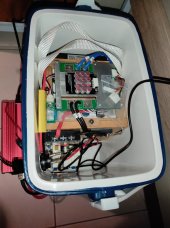
IMG_20220511_191840.jpg
My current portable all in one solar system with a JBD smart BMS + external active balancer. This external balancer solution is not ideal because I have to plug and unplug it whenever I need to top balance my cells. If i would let it plugged in all the time it would waste unnecessarily a lot of energy as well would bring my cells into disbalance.
I would love to order one of your active balancer BMS's if you would offer a low current version for about 70usd
 
Last edited:
Did they indicate why the heat function would make it more fragile? One possibility might be that pumping up to the 10A limit might cause internal thermal stress. I was planning to use the heat function for my boat land motorhome given that I am based on Washington state and have been known to travel in winter. That said, I would not hook the heating pads directly to the BMS. I would connect the BMS heat function to a SS relay that would turn the heating pads on and take the big currents.
There is no particular advantage in using a high-current SS Relay versus a Mechanical Relay in this application. An SS Relay would be critical for an application with rapid switching (a "dimmer" or motor controller). There are other situations where SS would also have big advantages. In this case, however, the SS Relay would need a heatsink, while an electromechanical Relay would not need one. (The heatsink puts out more heat, which is what we want - but it takes extra space and cost.) Also, most SS Relays are designed to switch AC loads at the moment when voltage is zero. You would need a Relay which supports DC output, such as this one: https://www.amazon.com/TWTADE-SSR-40-3-32V-5-60V-Solid/dp/B079BGGVYX/

For my own case (3 pads @22 watts each), I'll simply plug in an automotive 4-pin mechanical Relay. (i've got a bunch lying around, from some other projects.
 
A question for Nami, regarding this BMS function: Does the circuit "close" (activate) on the basis of temperature alone, or may it be configured to activate only for the case of low temperature WITH charging voltage present?

The latter case (with charging voltage detected) is much more useful for my 'production' configuration. Thank you, in advance!
 
Many thanks for your reply!
I would really love to exchange my JBD smart BMS with your 4s BMS with active balancer but sadly the price is just unreasonable, much too high. It costs even more than my four 53A EVE cells + JBD smart BMS together! Hopefully there will be soon a reasonable budget version, even just a 0.6A active balancer would be fine.
My current portable all in one solar system with a JBD smart BMS and external active balancer. External balancer solution not ideal because I have to plug and unplug it whenever I want to top balance my cells. If i let it plugged in all the time it wastes unnecessarily energy as well brings my cells into disbalance.
I would love to order one of your BMS's if not more than 60usd.
Visusolar: At 200A, this "super smart, with temp controller" BMS unit provides far more capability than your battery pack can use (being built with small 53Ah cells). I understand your complaint, that the price doesn't fit YOUR battery. And I agree with you, this upgrade makes no sense in that very small and inexpensive battery pack build. But the price is not 'unreasonable', within the high-current marketplace where this BMS will compete. (Your generalization 'sounded' unfair to me... but maybe my ears are just too sensitive at hearing that kind of wording issue :ROFLMAO: )
 
I would like a bms with balancing where it transfers the energy from the high cells to the low cells...
I'm no good with electronics, but why isn't that a thing? Why are all active balancers resistor packs?
 
Seems like you want a capacitive active balancer. Sadly it appears no one has offered one built into a BMS.
 
Visusolar: At 200A, this "super smart, with temp controller" BMS unit provides far more capability than your battery pack can use (being built with small 53Ah cells). I understand your complaint, that the price doesn't fit YOUR battery. And I agree with you, this upgrade makes no sense in that very small and inexpensive battery pack build. But the price is not 'unreasonable', within the high-current marketplace where this BMS will compete. (Your generalization 'sounded' unfair to me... but maybe my ears are just too sensitive at hearing that kind of wording issue :ROFLMAO: )
Yes, sure for the high current market a price like that is reasonable.

For the small current market, for which i obviously spoke, the 200a 4s version price is as you also said not justifiable. That's why I asked for/ requested a low current 4s version like i did above since i would also like to have a smarter BMS than my present one but for a price that's still reasonable. That's the whole point i want to drive, to offer a 4s BMS which fits the even bigger low current 4s market (in compare to high current 4s market) since this one doesn't. A 40A and 80A version would be great ?.

Opinion on the side, i would call it only "smarter" since it isn't smart yet concerning SOC especially over time. As well an active capacitor BMS version like requested above would be also smarter, more economical. There is room to become even smarter than this smarter one.
Jk is innovative and listens, so that's why I even bothered to request and suggest here something from them.
 
Last edited:
told me they have a new version 4s-8s coming in May. They say it will replace the JK-B2A8S20P
That is one BMS I would like to try on my below par 24v 280Ah (one three) battery banks ... for its' 2A balancer abilities ... plus good reviews. I have an experiment in front of me with one those $40 Heltec Active Balancers to pull back some peaker cells that jump up in voltage ahead of the others ... near my top charging voltage. From what I am learning; ... I would not leave these Active Balancers on 24/7, and will figure out an off and on switch ... I may, or may not automate for On at >3.4 volts or >3.35 volts only. If I had the newer JK BMS with active balance ... I would trust that on 24/7 ... as it looks like a great bet. I would like to read, and see pictures of the JK BMS ...LCD options. Looks like there may be two options ???, but I am still a little fuzzy on specifics. Hope someone can show us pictures of the JK BMS with LCD hooked up, and its plug in connections, and report of what it shows for battery information. I am currently using 2 Chargery BMS8T which has 5 pages of Battery info to look at, and two pages of configuration parameters to adjust and test, but only passive resistive for cell balancing, which one can turn on and adjust, most commonly used (I think) for the .3.4 volt cell voltage range :+)
 
Last edited:
I would like a bms with balancing where it transfers the energy from the high cells to the low cells...
I'm no good with electronics, but why isn't that a thing? Why are all active balancers resistor packs?
I thought active balancing is always moving energy!? So does the jk BMS not have a real active balancer integrated?
 
@Nami

1. What active balancing technology/method are your BMS's using?
2. Why does the balancing current go on and off constantly?
1.20min
3. Why do the cell voltages fluctuate rapidly while charging and balancing?
20.35min

Thank you
 
I thought active balancing is always moving energy!? So does the jk BMS not have a real active balancer integrated?
I believe JK only turns on balancing once cells are above 3.45 or some value (just like JBD but at much higher current), where as a haltec stand alone capacitive active balancer is on all the time unless you open the solder ports and add an automated switch.
 
Nami, I have one more question of general interest:

Does the heater port activate on the basis of temperature alone, or does it activate only for the case of low temperature WITH charging voltage present?
 
Two questions.
1. Andy at Off grid garage tested the new JK-B2A8S20P-H BMS's in a 4s setup and it did everything as advertised... except for the loss of magic smoke from one of the 20 discharge Mosfets during a 205A disconnect. It still worked perfectly after that while running on the remaining 19. Any thoughts on that partial failure?

2. The documentation for the JK-B2A8S20P-H "Doesn't Support Series Connection and parallel Connection". Why is that? I want to use 8 280A cells to create a 560A @ 12v battery bank and have been debating 2p4s with one BMS or two stand-alone 4s batteries each with its own BMS and then parallel them by connecting to a common charge buss. Not sure where to go with this now.
1.MOSFET is a chip used to protect BMS with 20 on it. This allows the BMS to charge and discharge 200A continuously or up to two minutes at 350A. If a MOSFET is destroyed, the overcurrent capacity on behalf of it will be reduced. In this case, it is recommended that the customer replace the new MOSFET.

2.Doesn't Support parallel Connection
(If your batteries are not consistent,
It is not recommended to link two or more BMS battery packs
Parallel Link to a Load)
Due to the discharging rate and battery consistency problems, which can cause different voltage to the battery pack without access, it is easy to cause the voltage of the high voltage battery pack to be reversed back to the low voltage battery pack. Therefore, we do not recommend parallel operation when the customer's battery consistency is insufficient.
On #2 I am not sure I understand your statement. If two battery packs each with their own BMS are connected in parallel at the - & + buss bars, the BMS is protecting each regardless of what the other is doing, is it not?

For easy math let's assume we are using (8) 100A cells.
  1. Are you talking about a 2p4s battery where pairs of 100A cells are connected parallel to each other to form 200A pairs. These (4) 200A pairs are then connected to each other in series to create a 200A 12-volt battery. This whole block is then connected to a single BMS which will monitor and protect all (8) cells. In this situation, if the cells are not carefully matched, there could be some issues with keeping the cells balanced but in any battery we should try to match the cells.
  2. Are you talking about a 4s battery where (4) of 100A cells are connected to each other in series to form 100A 12-volt battery with a BMS. Then two of these 100A 12-volt batteries are then connected to the + & - buss bars to create a 200A 12-volt battery capacity. In this situation, every one of the (8) cells is being monitored by a BMS and one battery / BMS will not know or care what is happening on the other except that the loads and charging will be 1/2 the amps in the total system which seems like a good thing to me.
In scenarios #2, even if the cells in one battery are much different than the cells in the other, It does not really make much difference because each BMS is controlling its own cells. In one of Andy's Off-Grid videos, he parallel connected a 5A battery with BMS to 280A battery with BMS and put them his normal torture testing. In all cases the two batteries stayed at the same voltage because of the parallel connection and as expected, the big battery supplied 98% of the current and the little one 2%. He even discharged one of the batteries separately so that they were out of balance with each other and then reconnected them in parallel. When they were connected, there was a little bit of static charging of the lower battery and as they were discharges towards the low voltage cutoff level, the weak battery took progressively lower percentages of the charge and then went off line and left the full load to the stronger battery. I do not see a problem with that.
 
I saw this video,
I thank Andy for the test,
I also understand the principle that the discharge rate of batteries in the storage state is slower, and that the discharge rate of batteries is faster and the imbalance is more pronounced when used with motors.
Not everyone follows theory.
So to prevent BMS damage,
We do not recommend parallel operation for customers.
Wow… so, in essence, you can only use this BMS in a single battery configuration.

So, if more Ah is needed, you have to connect them all through the single BMS.

If more amp output is needed, you need to choose a different BMS system.
 
Wow… so, in essence, you can only use this BMS in a single battery configuration.

So, if more Ah is needed, you have to connect them all through the single BMS.

If more amp output is needed, you need to choose a different BMS system.


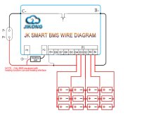
The best way is to connect the battery in parallel to a BMS and then to a load. As long as the voltage of the battery pack is 12V, a BMS can be connected. The BMS has little relationship with the capacity of the battery, because the active balance current of this BMS is only 2A; Therefore, the larger the capacity of the battery, the slower the balance efficiency will be. You can connect 4s1p, 4s2p or 4s3p to a BMS. A connection like a photo.
 

Attachments

  • 4 - 副本.jpg
    4 - 副本.jpg
    192.4 KB · Views: 55
Back
Top