diy solar

diy solar

JK: Abnormal Current Sensor

burgerking

New Member
Joined
Apr 6, 2022
Messages
368
Location
Subic, Philippines
I could not make out what this "Abnormal current sensor" issue is all about.
1656946260065.png

Any idea?
It comes and goes and I have no idea what is happening.

Thanks
Dan
 
Chased that down and eliminated it.
The Advanced Settings defaults SUCK ! Just look at the operational temp ranges for LFP No Charging below 0C is what it should be & Hi-Temp cutoff is MAX at 60C and they have it higher. Other stuff is just as goofy.

I run a Bank in with several packs in Parallel, a Samlex EVO Tier-1 Low-Frequency Pure Sine Inverter (costs the same as 2 AIO's)

Have a Look at the BMS Setting in this thread... Pint It (Probably best) or whatever and try to match the settings

The Firmware on the BMS' will be updated soon and a new manual is in the works as well... When that will appear, I dunno.
Good Luck Hope it Helps
 
You mean to say this error is Temperature related?

I had my default max temp at 40c, min temp at 10c; the temp probes are tucked between the cells albeit sensing only 8 cells.

This error occurred at the time when cells were fully charged, sometime 2PM; Deye is set to give 80A, while JK is set to receive 100A.
1656973252626.png


I am using:
1656973371144.png
Now I wonder why Manufacturing Date is the date of the pack installation.
 
From the Serial NUmber, your Build Date is 4180
Manuf Date is the date you first turned it on, being fixed.

NO "You mean to say this error is Temperature related?" is NOT related to Temperature !, but it is a prominent error in the default setting so I used it as an axample.
 
Hi everybody,
I have two JK-BMS
  1. JK-B2A24S15P for 16 x 280Ah Lifepo4
  2. JK-B2A24S20P for 16 x 310Ah Lifepo4
These two batteries are connected in parallel.
For a few last months everything works fine, but today I spotted on both bms-es "loop" of these two errors as well

abnormal current sensor abnormal release of current sensor abnormal current sensor abnormal release of current sensor

Unfortunately, i didn't check the firmware version.
Does anybody understand what these particular errors means?
 

Attachments

  • 20220724_133650.jpg
    20220724_133650.jpg
    258.7 KB · Views: 10
Last edited:
I have three battery banks in parallel. Two of them are using JK-B2A24S15P and JK-B2A24S20P. The third bank is using different BMS. The reported problem is not related to the parallelization of the banks but rather to the technical way how JK BMS measures current. They are doing low frequency sampling of the current and then post-processing the sequence of samples to come up with the current reading. If the sequence of samples contains alternating positive and negative values, this error is shown. Such regular fluctuation between positive and negative values happens usually if your inverter load is high enough and is very close to your PV power. MPPT is providing DC voltage, but inverters with higher loads cause consumption ripples on battery side with frequency two times higher than output AC frequency. The inverter has large capacitors inside but they are not able to smooth high loads ideally and the ripple is propagated to the battery connection. In such case, your battery bank is then working as very large capacitor for the system. When the AC output is close to 0V, MPPT delivers incoming current to your battery bank. When the AC output is close to its maximum voltage (positive or negative), current consumption from the battery input is higher than the one delivered from MPPT and thus the remaining current is drawn from your battery.

This error on JK BMS is not causing any issues. It automatically disappear when the fluctuation between positive and negative samples is gone. The only negative effect I found so far is that this affect also the remaining AH capacity calculation inside JK BMS. When this error is active, the remaininig AH capacity is not computed correctly. To have proper estimation of the battery remaining capacity you need a device with high frequency sampling to acumulate proper AH remaining capacity.
 
@ Dave21:
Clarity :
A Complete Battery is a collection of cells with BMS which operate as an Independent Entity.
A Bank is a collection of Complete Batteries connected in Parallel on a Common DC Bus operating in tandem dividing Load & Charge.

NEW JK-BMS Manual V: 2.2 2022/07/22
See Other links in my Signature as well.

Steve_S
 
Hi everybody,
I have two JK-BMS
  1. JK-B2A24S15P for 16 x 280Ah Lifepo4
  2. JK-B2A24S20P for 16 x 310Ah Lifepo4
These two batteries are connected in parallel.
For a few last months everything works fine, but today I spotted on both bms-es "loop" of these two errors as well

abnormal current sensor abnormal release of current sensor abnormal current sensor abnormal release of current sensor

Unfortunately, i didn't check the firmware version.
Does anybody understand what these particular errors means?

Welcome to the mysterious "abnormal current sensor" problem.
Did it occur after a full charge too?
 
Welcome to the mysterious "abnormal current sensor" problem.
Did it occur after a full charge too?
I observe this issue anytime until the battery is full. With the full battery, MPPT delivers power just for the load. At max there are observed negative ripples on the battery end. Thus the condition for alternating positive and negative low frequency sampling of the current are not met. This issue is simply bad design of the current sensor in JK BMS. To have proper coulomb (AH) meter and also current value, there should be about 1 ms sampling of the current flow for the systems with 50/60 Hz output (about 10 times higher than 100/120 Hz ripple frequency propagated from higher loaded inverter where the internal bus and battery capacitors are not able to smooth fluctuations).
 
I could not make out what this "Abnormal current sensor" issue is all about.
View attachment 101265

Any idea?
It comes and goes and I have no idea what is happening.

Thanks
Dan
I have the same problem. Also my Current Reading on the "Main Page" shows the real current for about 30seconds before dropping down to zero again. But in Reality there are 30A incoming...
 
I have the same problem with the JKBMS as described in this thread :/

@Dave21 you talked about the inverter too close to the BMS/battery.
I am seeing som strange voltage fluctuation in the BMS when the inverter is on.
Do you think my problem below can be caused by the inverter being too close to the BMS ?

I have made a new thread with pictures and description.
I have the same problem with a JK with older firmware, is not distance related, my inverter is 4 meters from batteries.
 
i'm having the same issue. hopefully it is truly a software issue and none of the hardware is suffering. why in the world the jk has a 50 item limit in the system log and why they use a horrible timestamp notation (timestamp is counting backwards to the fault) -- i cannot for the life of me comprehend why the designers did this.
 

Attachments

  • IMG_5822.png
    IMG_5822.png
    1.1 MB · Views: 9
  • IMG_5823.png
    IMG_5823.png
    709.2 KB · Views: 13
  • IMG_5824.png
    IMG_5824.png
    951.6 KB · Views: 11
  • IMG_5825.png
    IMG_5825.png
    583 KB · Views: 13
  • IMG_5826.png
    IMG_5826.png
    625.4 KB · Views: 12
i'm having the same issue. hopefully it is truly a software issue and none of the hardware is suffering. why in the world the jk has a 50 item limit in the system log and why they use a horrible timestamp notation (timestamp is counting backwards to the fault) -- i cannot for the life of me comprehend why the designers did this.
One word: Chinese!!!
Horrible Timestamps, horrible Software, no updates, ...
 
The logs are NOT ROLLING they hit 50 entries and lock up....
They know this, they said it would be fixed and almost a year later NADA !

Have a look at my settings and info to set your BMS up. The settings are for 24V so X2 for 48V or ÷2 for 12V.
NOTE the Temps etc are messed up by default, you need to change them.... the devil is in the details.

PS: I am the Manual Editor and have posted much about these here, including solving this issue.

Hope it helps, Good Luck.
 
.... They are doing low frequency sampling of the current and then post-processing the sequence of samples to come up with the current reading. If the sequence of samples contains alternating positive and negative values, this error is shown. Such regular fluctuation between positive and negative values happens usually if your inverter load is high enough and is very close to your PV power....
You are right. I compared my database records with jkbms's "timestamps" and they happened just at the time of changing the current sign (direction).
.....
This error on JK BMS is not causing any issues. It automatically disappear when the fluctuation between positive and negative samples is gone. The only negative effect I found so far is that this affect also the remaining AH capacity calculation inside JK BMS. When this error is active, the remaininig AH capacity is not computed correctly........
Tanks for this idea.
It is clear now why I have to "calibrate" SOC every 3-4 weeks as it goes lower and lower against displayed.
 
Hi, I spent some time investigating this issue. I wrote a program that captures time series of the BMS data (batmon-ha).

Dave21 has already pointed it out.
This is a software issue, specifically a design issue in the JK firmware.
It happens when the superimposed AC current has a higher amplitude than the DC current.

Inverters consume DC+AC current. 50 Hz inverters produce a 100 Hz sinusodial current wave form that is superimposed to the DC part, which can look like this (captured with an oscilloscope and Riedon SSA-100):
1700070920474.png
(yellow: inverter input current, red inverter output current. Note that this is a cheap china inverter and the yellow wave form should actually be a sinus, with proper filter design).

If the inverter runs during the day, the solar current pushes the yellow curve down until it crosses zero. So we actually microcycle the battery at 100 Hz, discharging and charging it a bit. This does not significantly reduce battery life though, see this paper.
And it actually shouldn’t be a problem for current sensors with proper noise and aliasing filters.
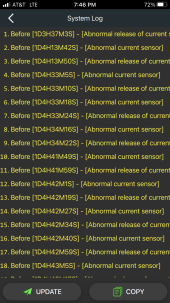
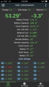
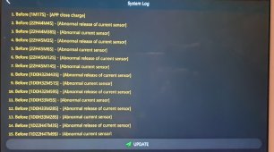
However, the JK firmware thinks there is a problem, because it permanently reads positive and negative currents. Once you disconnect the solar panels, the BMS should start reporting the correct current.

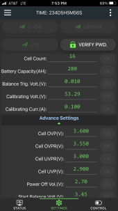
So we should ask the manufacturer to fix this problem with a firmware update (is this even possible on a JK?)

Another solution would be a hardware hack. We could add a small capacitor and resistors to the inputs of the current sensor that smoothes the 100 Hz out. I might try this out and will get back then.
 
Back
Top