diy solar

diy solar

JK-B2A25S60P wiring and starting

Prof Chill

New Member
Joined
Apr 11, 2022
Messages
15
I have a JK-B2A25S60P that I’m trying to puzzle my way through. Most of my electronics knowledge has come from building circuit boards for things like guitar pedals and stepper motors 20 years ago. I made a solar setup about 5 years ago, but it was fairly small and used lead acid batteries. The system I’m building will run a 20kw sailboat motor. I’m new to the LiFePo, high amp world.

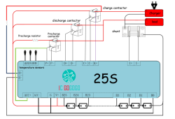
When I look at the diagram from the JK manual, it almost looks as if the yellow lead from the V- terminal goes directly into the B- terminal, bypassing the main battery negative, and that the B- lead goes to the battery side of the shunt. This can’t be correct, can it? Shouldn’t the V- and B- terminals both go to the negative battery terminal or negative bus?

I’m also wondering how to get the thing to start up. This BMS doesn’t seem to have the same wiring configuration as the other JK BMS’s without external contactors. How do I add the 9v battery in series to get the BMS to start up? What terminals do I cross with the leads from the 9v battery?

Amy help you can give me would be hugely appreciated. The documentation for it is really sketchy.

JKBMS500-A.png
 
That's really helpful, Ray, and thanks for the email link. But the pinout isn't exactly the same on mine. I don't have an "ACC+" or "ACC-", or a "G". I do have a pin labeled "5v" that I'm wondering if it's where I'm supposed to add 5v to kick start the unit.

Anybody else have any thoughts on this?
 
I have the same BMS to upgrade an older failed unit.

I found this diagram which is in English.

1677287136109.png
 
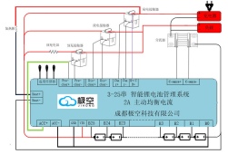
The diagram below is from a Chinese manual I found for the JK-B2A25S-RP which has English labelled pin outs that actually match what the cables are labeled with. This is what I was guessing from the diagram posted just prior, but nice to have confirmation.

I am going to install likely today to replace my failed BMS - Balancing and power out to the display is not working. Using only one battery relay only as I have an integrated inverter/charge controller. If I had a separate charge controller I would use another relay for the charge function. I may add the charge relay in the future as I will occasionally charge the battery with a power supply as my setup is a whole house battery backup vs solar and I can run the external charger through the charge relay which will be more convenient. Using the Discharge relay outputs only, and I will wire K+/C to the load side of the Discharge relay. I am Wiring all the grounds to B-, not using the pre-Charge feature at this time so not wiring ACC+

1677342591444.png
 
I have a JK-B2A25S60P that I’m trying to puzzle my way through. Most of my electronics knowledge has come from building circuit boards for things like guitar pedals and stepper motors 20 years ago. I made a solar setup about 5 years ago, but it was fairly small and used lead acid batteries. The system I’m building will run a 20kw sailboat motor. I’m new to the LiFePo, high amp world.

When I look at the diagram from the JK manual, it almost looks as if the yellow lead from the V- terminal goes directly into the B- terminal, bypassing the main battery negative, and that the B- lead goes to the battery side of the shunt. This can’t be correct, can it? Shouldn’t the V- and B- terminals both go to the negative battery terminal or negative bus?

I’m also wondering how to get the thing to start up. This BMS doesn’t seem to have the same wiring configuration as the other JK BMS’s without external contactors. How do I add the 9v battery in series to get the BMS to start up? What terminals do I cross with the leads from the 9v battery?

Amy help you can give me would be hugely appreciated. The documentation for it is really sketchy.

JKBMS500-A.png
In your diagram and in other references B- goes to the terminal of the first negative battery, along with the output cable. V- also goes there. You can crimp both into the same connector for the battery terminal.
 
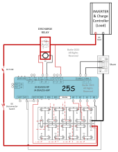
I have the 2A balance version of this BMS and just wired it in yesterday. Everything works fine except the discharge relay does not power up. The relay energizes and passes the main current from the battery if I put 12V DC to the relay from a separate power supply so it isn't the relay. It is likely some of the undocumented wires not wired properly, but does anyone have any ideas?

This is my setup - UPDATED WITH CORRECTIONS BELOW!!!
1677503686674.png
 
Last edited:
I have the 2A balance version of this BMS and just wired it in yesterday. Everything works fine except the discharge relay does not power up. The relay energizes and passes the main current from the battery if I put 12V DC to the relay from a separate power supply so it isn't the relay. It is likely some of the undocumented wires not wired properly, but does anyone have any ideas?

This is my setup
View attachment 137074
I have a similar problem and strangely it turned out that you have to respect the polarity of the relay... !
 
I have a similar problem and strangely it turned out that you have to respect the polarity of the relay... !
Thanks. I get no voltage from the relay wires coming from the BMS. There are a lot of unused wires in the extra connector where the relay leads are. Can you share how you wired it if you have this BMS? :) I can post the leads that are not wired later if that helps.
 
Thanks. I get no voltage from the relay wires coming from the BMS. There are a lot of unused wires in the extra connector where the relay leads are. Can you share how you wired it if you have this BMS? :) I can post the leads that are not wired later if that helps.

Hi Burke - I also have an inverter charger, and also am currently using a single contactor, but wired into the charge leads from the BMS instead of the discharge ones. Do you have the system working otherwise? The BMS app will allow you to turn the charge and discharge capacitors on at will. Is yours possibly set with the discharge off?
 
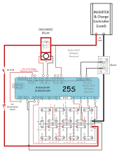
I have figured out how to power up the relays by testing the unused wires out of the BMS. Apparently the Pre-Charge+ cable is also where the V+ comes from to power the relays (Charge/Discharge/Pre-Charge). I wired the ACC+ wire to the Pre-Charge+ wire with a crimp connector (I am not using pre-charge circuit), and I got the +12V at the Charge and Discharge relay wires when I use the app to turn them on and off. Final diagram is posted below. Works perfectly now. Apparently the Pre-Charge+ takes the Output from ACC+ for the other relays @ 12V. They show this in the diagram (green wire from ACC+ to Pre-Charge), and it isn't obvious what is happening but after thinking about it it seemed like it must be power in for the relays. I tested the hypothesis and it was correct. Happy now!

1678035947982.png
 
Last edited:
Hi Burke - I also have an inverter charger, and also am currently using a single contactor, but wired into the charge leads from the BMS instead of the discharge ones. Do you have the system working otherwise? The BMS app will allow you to turn the charge and discharge capacitors on at will. Is yours possibly set with the discharge off?
My issue was not bringing the ACC+ power to the Pre-Charge+ line for sure. The other point you bring up is an interesting one though, which relay to use if you are only using one (Charge/Discharge). The BMS will shut down the battery if it sees a bad situation. I am assuming that the worst case will be from discharging with a low cell as being the most likely, but it could easily be a bad charging situation as well. I am going to think about some relay logic to use both charge and discharge outputs with one relay...
 
My issue was not bringing the ACC+ power to the Pre-Charge+ line for sure. The other point you bring up is an interesting one though, which relay to use if you are only using one (Charge/Discharge). The BMS will shut down the battery if it sees a bad situation. I am assuming that the worst case will be from discharging with a low cell as being the most likely, but it could easily be a bad charging situation as well. I am going to think about some relay logic to use both charge and discharge outputs with one relay...
I'm thinking that I'll tie my positives from the battery to a bus, wire the inverter charger through the charge contactor, and then run all my loads to a discharge contactor wired to the positive bus. If the inverter sends too much juice to the battery for some reason, the BMS will shut it down via the charge contactor, but still giving me power to run things. If the loads draw too much amperage, the BMS will shut it down via the discharge contactor, leaving the battery free to charge. Contactors are pricey, but they're not *that* pricey. I'm still not sure that I'll use the pre-charge contactor and resistor, because I'm still not sure what its job is or if I need one.
 
I'm thinking that I'll tie my positives from the battery to a bus, wire the inverter charger through the charge contactor, and then run all my loads to a discharge contactor wired to the positive bus. If the inverter sends too much juice to the battery for some reason, the BMS will shut it down via the charge contactor, but still giving me power to run things. If the loads draw too much amperage, the BMS will shut it down via the discharge contactor, leaving the battery free to charge. Contactors are pricey, but they're not *that* pricey. I'm still not sure that I'll use the pre-charge contactor and resistor, because I'm still not sure what its job is or if I need one.
The Pre-Charge would bypass the main charge and discharge contactors to charge the capacitors in the inverter. It needs a resistor to prevent a large inrush of current which is very hard on contactors, and can cause damage. I would guess that when you turn on the BMS there is a timed function that turns on the pre-charge relay first, then opens the main charge/discharge relays. I have a separate pre-charge circuit built into a disconnect box so I don't really need it.
 
The Pre-Charge would bypass the main charge and discharge contactors to charge the capacitors in the inverter. It needs a resistor to prevent a large inrush of current which is very hard on contactors, and can cause damage. I would guess that when you turn on the BMS there is a timed function that turns on the pre-charge relay first, then opens the main charge/discharge relays. I have a separate pre-charge circuit built into a disconnect box so I don't really need it.
How big of a resistor are we talking?
 
A 100W, 30ohm resistor is a decent size for a 48V battery bank. Start of inrush will be about 99W by my calculation. Doesn't have to be a nominal resistor, just a resistive only load, and there's a lot of flexibility in what is acceptable.
 
Back
Top