diy solar

diy solar

JK BMS 4.3" LCD screen wire diagram (not included in my box

OffGridIdaho

Hobby Farm in N Idaho
Joined
Jun 18, 2020
Messages
224
Location
N Idaho
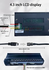
Well since I spent 5 days trying to figure out my red/yellow (WTF didnt they use red/black like the rest of the planet??) wire delima on my screen I thought I would post this. I did NOT want to smoke my BMS as they are 1 month to get a new one.

AND.............

If you are making a screen for a BMS that is used on 12v/24v/48v cell-packs why not have a power supply inside the screen that can use 12/24/48v???????

BUT NOOOOOOOOOOOOOOOOOOOOOOOOOOOOOOOOOOOOOOOO

They made the ground wire -------->>>>>>>>>YELLOW and only allow 12v voltage. I mean WHY NOT MAKE IT 5V to really mess with the stupid Americans. Gotta love the chinese!
 

Attachments

  • 61o0OMo2DEL._AC_SY879_.jpg
    61o0OMo2DEL._AC_SY879_.jpg
    64.6 KB · Views: 88
  • bms wires2.jpg
    bms wires2.jpg
    165.7 KB · Views: 89
Last edited:
Yellow is the new black (the TV show was wrong).

The ABYC specifies that now and I was surprised when my boat, built in the US in 2016, had all yellow negative wires.

But I agree about the voltage nonsense.

My JK BMS is on its way from china and although I understand 16s wiring for it I’m sure I’ll have a YT video going during the “wake up” nonsense.

I did not order an LCD screen.
The screen has the on off button. The bms does not.
That yellow for ground nonsense after 90 years of using black has to be (CENSORED) Im not allowed to talk about this topic.
 
I just got a new Jk BMS 2a active balancer, 8s to 20s and it didn’t come with the turn on/off switch (they forgot about it). I have the LCD connector does anyone knows which contacts I need to do in order to switch it on? Thanks!
 
Tried to connect K+ and K- with a 100k ohm resistor but doesn’t seem to work. Maybe I just need to try to do it without the resistor?
 
Back
Top