diy solar

diy solar

JK BMS as a random number generator?

farnham

New Member
Joined
Nov 15, 2021
Messages
4
I am using a JKBMS in my van with a 8s 280Ah battery. The battery powers a Victron Multiplus2 3000/24, connected by (very) short and thick low-resistance wiring. The amps are lowish in the sub 100A range normally due to the 8s setup. All wiring and connections are super-cold - just checked it again by IR camera.

However, all readings of the JK BMS are seriously noisy. When the inverter is drawing 2kW of continuous power (water kettle - pure linear load), the current reading fluctuates quickly in the range from 30A to 120A. Unfortunately, the total and cell voltage readings are also affected. The cell voltages jump up and down by +-100mV, so 200mV in total. I begin to doubt that there is any reasonable OVP/UVP action possible if the raw readings are so noisy.

The readings are also a considerably noisy with the inverter switched off and just running some (dimmed) LED lights, a Cerbo and a diesel heater (genuine Espar).

Anybody out there with a JK BMS performing considerably better? I have bought my JK-B2A8S20P in May 2022 via AliExpress - is there a chance that a newer hardware revision is available, that has been improved in between?
 
I think your bms is defect, correction: more defect than normal.

It is normal for jk bms to show erratic current reading during load from an inverter. Also SoC calculation is way off.
 
My JK produces consistently accurate current and cell readings both under load from the inverter and while charging. No measurable jitter or inaccuracies. The SOC measurement is never perfect, but isn't a bad estimate either.

What farnham is describing is nothing like the expected behavior, and sounds like a defective unit. Either that or there's a lot of interference coming from another source.
 
I am using a JKBMS in my van with a 8s 280Ah battery. The battery powers a Victron Multiplus2 3000/24, connected by (very) short and thick low-resistance wiring. The amps are lowish in the sub 100A range normally due to the 8s setup. All wiring and connections are super-cold - just checked it again by IR camera.

However, all readings of the JK BMS are seriously noisy. When the inverter is drawing 2kW of continuous power (water kettle - pure linear load), the current reading fluctuates quickly in the range from 30A to 120A. Unfortunately, the total and cell voltage readings are also affected. The cell voltages jump up and down by +-100mV, so 200mV in total. I begin to doubt that there is any reasonable OVP/UVP action possible if the raw readings are so noisy.

The readings are also a considerably noisy with the inverter switched off and just running some (dimmed) LED lights, a Cerbo and a diesel heater (genuine Espar).

Anybody out there with a JK BMS performing considerably better? I have bought my JK-B2A8S20P in May 2022 via AliExpress - is there a chance that a newer hardware revision is available, that has been improved in between?
Could you send us a picture of the BMS and it's connections?
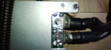
The reason I ask is because it's very easy to get the lugs to touch the MOSFETS. This will cause all sorts of problems.
They should have spaced the terminals farther away from the FETS. It a pain especially if you use large lugs.

I put some insulation between the lugs and FETS, just for added safety.
 
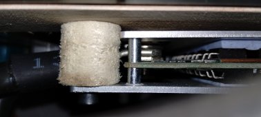
Useful photos are unfortunately next to impossible to take - the BMS is mounted upside down on the rear side of the battery with only a few inches of space to the wall. However, I can peek into the gap between FETs and the wire lugs - looks good to me. I remember, that I have ordered three diferent kinds of wire lugs until I found one that had a comfortable gap to the FETs and all other parts close by.

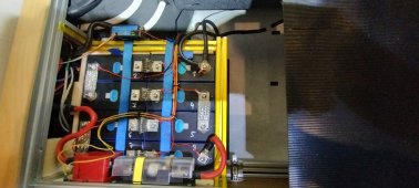
However, while trying to take photos, I discovered one detail that might be not ideal: the positive supply shares a common fuse with the Victron SmartShunt. The fuse is probably not too oversized. This might be a thing to be improved.

Anyway, did anybody buy a JK BMS recently that is performing well? Where did you source it from? Having a spare is probably not a bad idea generally.
 

Attachments

  • IMG_20230322_173004037.jpg
    IMG_20230322_173004037.jpg
    205.8 KB · Views: 25
  • IMG_20230322_173122387.jpg
    IMG_20230322_173122387.jpg
    137.7 KB · Views: 26
  • IMG_20230322_174408407_HDR.jpg
    IMG_20230322_174408407_HDR.jpg
    246.7 KB · Views: 26
Just got a B2A20S20P today and put it in for a quick test. Current reading is rock solid now, as is the total voltage. Obviously, JK has introduced some filtering here in the recent units. Also like the fancy switch that is included now.

Cell voltage is still fluctuating a bit, but within a reasonable range of less than 20mV. After seeing that, I switched the multimeter to AC to measure the true ripple voltage and got 18mV RMS per cell / 160mV total / approx 0.5% with the Multiplus running at 2kW, which is completely fine IMHO.

Just opened the "faulty" unit. PCB looks very nice, no obvious damage, no signs of heat or bad soldering. The PCB revision says "JK-B2A8S-20P_V9.0".
 
Last edited:
Back
Top