diy solar

diy solar

JK BMS Cell Count Problem on B2A24S20P

I have another thought. The 16 cells are connected in two groups of 8 each. Within each bank of 8, they are connected by bus bars, but the two banks are connected by a cable. Would that make a difference because cell 9 is the first one in the second bank and cell 8 has also gone bad twice. Cell 10 has also gone bad. No cells on the far ends have had problems. Not sure why that would affect the balance current, but who knows?
 
Last edited:
That should not make a difference but the fact that it has to keep balancing sounds like it is burning up the balance resistor.
You would like to think the BMS would protect itself from situations like that but well...
 
That should not make a difference but the fact that it has to keep balancing sounds like it is burning up the balance resistor.
You would like to think the BMS would protect itself from situations like that but well...
That's what I thought. It is burning up the balance resistors even if I lower the balance current. Cell 9 is always involved. The other cells are close by. I have been through 3 JK BMS units and they all have the same issue so perhaps the arrangement is a problem or cell 9 itself is defective.

Hypothetically speaking, if cell 9 has internal problems that cause it to draw too much current before the BMS can respond it could cause problems. I have no way of testing that but it is an idea. If for example cell 8 was providing balance current to cell 9 when cell 9 had its issue, then both cells balance resistors would be fried if it happened too quickly for the BMS to respond.

The problem with that idea is that it should happen as soon as I start it up unless there are some dynamics within the cell that shift over time.
 
Last edited:
it might help to install some. if there is some sort of cell surge on the balance lead it would help protect the BMS if thats the issue? also might help with diagnostics if you are blowing fuses on that suspect cell 9?

I may have to consider fuses if I cannot figure out why the balance resistors are getting fried.
 
I may have to consider fuses if I cannot figure out why the balance resistors are getting fried.
Be careful about fuses. They can be a source of a new problem of intermittent interruption.
The the mini in-line fuse holder(pictured) works well…. for a while then un explained interruptions to my Solar Assistant from my new buck converter.
What happened is some sort of corrosion setup between the nickel plate for the fuse end and the brass contacts. I cleaned the junctions and used dielectric grease and they have been fine for over a year. A better way and much more secure is to solder and heat shrink the fuse.
IMG_1096.jpegIMG_1097.jpegIMG_1016.jpegIMG_1019.jpegIMG_1020.jpeg
 
Greetings all. Long-time listener, infrequent caller.
I have just received and installed a B2A24S20P for my 16s LiFePO4 setup. I also have a missing cell (and the alert that says cell count doesnt match setting). I redid the crimps on the wire on that cell and it did not resolve. The curious thing though is that as per the wiring instructions B+ gets its power from cell 16pos and my total pack voltage shows up as 50.3v which is the voltage of 15 cells, not 16.

Sent an email to support so... ?

Cell16_voltage.jpgCell15_voltage.jpgScreenshot_BMS.jpg

12x250 Watt panels
16 cell/ 48v
B2A24S20P BMS
Growatt 48V SPF 3000TL LVM
NYC and 25% off-grid :)
 
Total voltage is calculated as the sum of all cells, not the pack voltage directly.
Thanks. I had a suspicion that might be the case because it might have also explained the slight discrepancy between the actual voltage shown on the multimeter at cell 15 and the BMS shown total voltage of the 15 visible cells.

I guess now I am back to just troubleshooting why cell 16 is not showing up. Note: I am currently not connected to any inverter/charger. I just want to make sure the BMS set up was solid before introducing any large currents.
 
Thanks @upnorthandpersonal & @Quattrohead. I will pull the connector and trouble shoot at that end, After 10+ years of marriage I tend to always just assume I am the problem, it would be great if this time the problem is actually on the other end,

Stay tuned.
 
Thanks @upnorthandpersonal & @Quattrohead. I will pull the connector and trouble shoot at that end, After 10+ years of marriage I tend to always just assume I am the problem, it would be great if this time the problem is actually on the other end,

Stay tuned.
Checked pins and connectivity through the connector. All tested fine. Still no response from support or the vendor I bought it from (18650batterystore.com) about the "missing" cell. I just gave up and pulled out the JK BMS and went to an older ANT Smart BMS. My plan is to leave both BMS's connected and turn off active balancing while I continue to troubleshoot.
 
Last edited:
Checked pins and connectivity through the connector. All tested fine. Still no response from support or the vendor I bought it from (18650batterystore.com) about the "missing" cell. I just gave up and pulled out the JK BMS and went to an older ANT Smart BMS. My plan is to leave both BMS's connected and turn ogg active balancing while I continue to troubleshoot.
Delete
 
Had a JK arrive a few days ago, failed to see cells 8 and 9 as soon as it was turned on. Cells were all 3.300V +/- 5mv so below the balancing voltage and within a few milli volts anyway. Replacement is on its way after I gave the supplier pics to confirm the cells and harnesses were good to BMS and no pins on the BMS were bent, so it could only be the BMS.

So out of curiosity I opened up the BMS to take a look.

Found some faults.

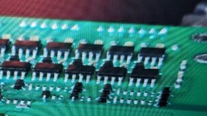
On Cell 8 balancer the 0.01R resistor had blown.

On cell 9 there is a large solder bridge between the capacitor and the 8 pin SMD pad, giving a direct route bypassing the cap.

I assume that if I can fix these issues then it may work, there is a spare resistor as there are 2 paths for Cell 8 which I can move to replace the blown one. I have a hot air soldering gun and a soldering microscope so can do that and remove the blob.

However I have found 2 more errors on the board that don't seem related to C8 or C9 but could cause issues.

one is a capacitor where a solder blob links the 2 ends making the capacitor bypassed.

This is fixable by removing the solder or replacing the capacitor.

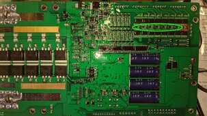
But for the second one I need confirmation as it looks to me that on the balancer side one chip has the capacitor and resistor positions reversed but that may be by design.

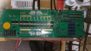
So could someone look at their board and in the red circled area are your caps and resistor orientation matching my pic or the rest of the cell balancers. The first pic is of the full board so you can recognise the board side, second is a close up of the parts that need confirmation, the reversed cap and resistors, resistor top, cap below are in the red oval, in the green oval the rest are all Cap top, Resistor below. If the pics aren't clear I can edit for a close up.
 

Attachments

  • full.jpg
    full.jpg
    460.8 KB · Views: 5
  • half 1 highlighted.jpg
    half 1 highlighted.jpg
    512.2 KB · Views: 5
Found a breakdown of the board on youtube and can just see the end 8 pin chip has the cap/res reversed as well. So either they are all defective or its by design, I will assume its by design but will open up the replacement to check it over before repairing the bad one.
 

Attachments

  • Youtube shot.jpg
    Youtube shot.jpg
    641.1 KB · Views: 3
Back
Top