diy solar

diy solar

JK BMS issue with charging

Most of mosfet style BMS will need charging and discharging enabled....otherwise if you enabled only charging and not discharging there will be 0.4-0.6V voltage drop across BMS.
This the nature of mosfet and you need to know that. Otherwise you may find yourself raising voltage over and once mosfet is sensing this will automatically switch discharging and delta V across will drop down to 1-2 mV and then you will have higher voltage than necessary. Not all mosfet BMS are the same but JK are one that you should be informed about it. It is always best to do all benchtop experiments with new BMS so you are familiar how it operates otherwise it will drive you mad.
 
Also some benchtop power supplies need V sensing and this will be only possible if you enabled discharging on BMS. Most of beginners and not very advanced users need to become familiar with all tools that they are using before they start messing with battery cells or battery pack voltage calibrations. Also if you are calibrating bms shunt make sure you are doing it with higher current and by using trusted instrument to make connections. I'm running on this issues daily from my customers and not well advanced user in building by themselves battery packs. There a lot of little details what seperate professional builders from beginners. So don't hesitate to ask questions and we are here tl learn from each other.
 
Not all mosfet BMS are the same but JK are one that you should be informed about it.

The JK automatically opens the charge and discharge MOSFETs (even if one of the functions is disabled) when there is a current flowing in the allowed direction. I don't remember the threshold, but it's around 1A or so...
 
The JK automatically opens the charge and discharge MOSFETs (even if one of the functions is disabled) when there is a current flowing in the allowed direction. I don't remember the threshold, but it's around 1A or so...
Current is irrelevant voltage has to increase 0.5 +/- V to trigger auto enable discharge and lower it down to 1-2 mV when discharge is is . And this could be dangerous for people who are not aware of this mosfet phenomena. So before starting to calibrate pack voltage or ramping voltage on the MPPT or power supply to overcome voltage drop ....make sure you are checking it will charge and discharge on.....
If voltage is lower because of bms mosfet losses across mosfet ( discharge off) it will not carry any current because voltage has to be higher for current to flow.
 
Whenever you turn BMS charging or discharging off you will have a diode voltage drop due to turned off MOSFET body diode. So generally, you do not want to turn either off unless you want no current, either charge or discharge. The extra diode drop will also drop your charger absorb and float voltage seen at battery.

The BMS current sensing firmware normally overrides your disable setting if you draw more than about 5 amps through BMS. This is to prevent BMS from overheating due to extra voltage drop. It may also override the disable if temp of BMS rises too much due to current x diode voltage drop.

It re-enables your disable setting when allowed direction current drops below 5 amp. There is a response time so with inverter ripple current you could get some of the disabled direction current for short periods as it crosses the direction threshold and add in the current detection delay response time. The MOSFET gate drive for the main switch MOSFET's gate control does not have very strong drive so the turn off and turn on time of the MOSFET's is not very fast.

Your issue is likely with disabled discharge turned ON, the charger is not detecting a battery voltage, so it doesn't turn on its charge current.

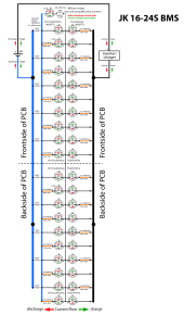
JK Active bal BMS MOSFETs.png
 
Last edited:
@RCinFLA i may be wrong about your statement but on my benchtop observation when discharge is turned off even if i increase current over 5A and voltage drop across is 0.6 V it will not start charging ( considering cells are not fully saturated at given voltage and benchtop power supply is set same as voltage measured before JK BMS. Initial drop across BMS will result in no current flowing because voltage is less than true battery pack voltage. Raising pack voltage on benchtop power supply above 2 V than pack voltage measured it will trigger automatically switch for discharge ON and voltage difference will drop to 1-2 mV , where now if this is not something user knows it will charge pack 2 Volts higher ( I'm talking about pack Voltage here not cells voltage). Please correct me if I'm missing anything in my observations.
 
I've written about this in the past here:


Andy from Off Grid Garage also showed this phenomenon - watch the "Discharge" status on the screen recording of the app:

 
In the first video it shows confused Andy. Start video at 9:00 timestamp.

At 13.31 timestamp is the critical action. He enables charging on BMS (discharge still disabled) and raises power supply voltage so charging current goes to 5 amp, and voltage drop across BMS goes from 360 mV to 3.5 mV.

To be specific, and because he did not know what was happening, he did not specifically look for what BMS current sense overrode the discharge disabled setting. At the 5 amps of charging current, just where he happened to set power supply, it was overridden.

At some point between 0 and 5 amps of charge current the BMS override of discharge disabled occurred. If you gradually raise the charge current and watch for when voltage across BMS drops to low level it will tell you the disable override current. So, my statement of 5 amps may not be accurate. It might take less current through BMS required to override the disable setting. The BMS needs some margin on getting too close to zero current since its current measurement at low current is not great and there is delay in its reaction time to turn it back ON.

Realize there are 20 large diodes in parallel during disabled setting mode. Because of the diode V-I exponential curve there will not be as much diode voltage drop at low currents. BMS net heating will be the diode drop times the BMS through current. Above about 10 amps it would begin to have significant heating so they need to turn the disabled MOSFET back ON to avoid the diode voltage drop additional heating.

 
Last edited:
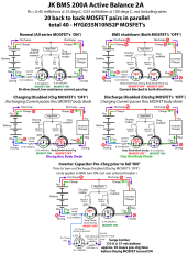
Maybe this diagram will help explain the charge/discharge disable function. The diagram at bottom shows the inverter capacitor pre-charge function which only occurs when BMS turns itself on. (it won't help limit current if you use your series circuit breaker when the BMS is already ON)

BMS charge-discharge Disable function.png
 
Last edited:
I have watched Andy video but my test is giving me different results. Will have to watch one more time when I get the chance to see where Andy and me are going different in observation. But for everyone else this is not something you should be worried about JK BMS it just needs attention to this .
 
And another unknown with Andy power supply is how accurate it is when voltage is adjusted under load. Most of expensive benchtop supply requires temporary lead removal before adjusting voltage...there are many unknown factors in his testing.
 
Andy still doesn't fully understand what is happening.

Instead of adjusting the power supply voltage he should have set power supply to desired absorb voltage, as if it was a normal charger, and use the variable current limit to adjust the charging bulk current allowed to go through the BMS, as if it is from a PV controller with variable PV sunlight power output.

If he did this, he would just see the voltage drop across the BMS suddenly reduce when the current reached the point where BMS overrides the disabled discharge setting. If he then adjusted current limit back down, he would see when BMS re-allowed the discharge disable and voltage drop across BMS would increase again.. This of course assumes battery state of charge is low enough not to limit the bulk constant charging current by getting too close to absorb charge voltage limit set on power supply.

The greatest ramification is if charger relies on current taper off charge termination from absorb cycle. As soon as taper current drops low enough the BMS voltage drop will snap increase by diode drop and the charger may immediately exit absorb cycle prematurely.

At a high enough current demand through the BMS, the BMS must override the disabled discharge or the BMS will overheat. All BMS's that allow independent charge/discharge disable must do this or risk overheating BMS.

This all applies the same way to discharge current if only charging is disabled. If inverter draw 50A to 100A with the diode drop in BMS still engaged the BMS will roast in a few minutes. More likely, the BMS over temp sensor will shut down the BMS and the inverter.
 
Last edited:
Instead of adjusting the power supply voltage he should have set power supply to desired absorb voltage, as if it was a normal charger, and use the variable current limit to adjust the charging bulk current allowed to go through the BMS

Which is what he did in the video I posted, at the time stamp it's at.
 
Back
Top