diy solar

diy solar

jk bms not showing discharge watts or amps

ajtarnas

New Member
Joined
May 30, 2022
Messages
30
Vendor ID: JK-B2A20S20P
Serial Number: 2052316096
Hardware Ver: V10.XW
Software Ver: V10.09
Version: V4.8.5
iphone se2020 ios15.5

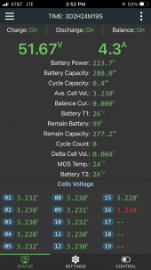
i have a jk on my 16s 280ah 14.4kwh EVE cell LFP bank, just like offgrid garage.

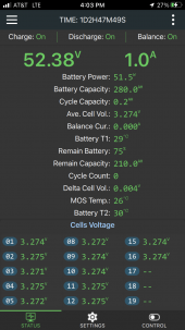
the bms app on my iphone does not show discharge current or watts. i'm used to the xiaoxiang bms app and the overkillsolar bms (rebranded JBD bms), which shows net charge or discharge in watts.

i see videos of the jk bms app showing net charge or discharge in positive or negative amps -- less useful and silly in my opinion, but acceptable. but my app does not show discharge, only positive amps for charging.

i do not have a shunt on the system. the jk instructions do not seem to call for one. am
i missing something? (@Nami is this your area of expertise?)
 

Attachments

  • FBDA2B37-5B05-4C40-9FA0-DD6DF5352440.png
    FBDA2B37-5B05-4C40-9FA0-DD6DF5352440.png
    742.4 KB · Views: 31
Last edited:
1662936272690.png

Are you saying that the Current on display is always Positive? never have you seen it in negative?
Maybe it is because your SCC is charging the pack?

Get 4 pcs of car headlight bulbs in series (like what Andy used) and discharge your battery pack with it.
 
yep, never negative, always positive. and the SOC is completely off. i live off grid and need the power for tonight but tomorrow i will discharge the pack.

right now i think i'm using about 400w and it's very cloudy outside with ~200w coming in. the jk only shows what's coming in from my panels, it's not subtracting the discharge/load power. the jk thinks the battery is almost full and has reported no negative amp number all day. the cell voltage of 3.23v suggests i have abt 100ah left (~5000wh, ~30%) or possibly less.

(i've lived off grid for five years -- i think i've ruled out any silly problems. i'm using a powmr 60a mppt -- the classic $100 version. there are 1200w of panels hooked up in 3p2s but they are horrible "240w" trina panels from santan -- usually get 120w each but spike to 200w on occassion, making it hard to stay inside the powmr's limits).
 

Attachments

  • EF8E01DB-6FE3-4577-9D13-3A183D04D280.png
    EF8E01DB-6FE3-4577-9D13-3A183D04D280.png
    747.8 KB · Views: 12
  • 5EEF8A83-DBB8-472F-AAB2-3BF94A093890.png
    5EEF8A83-DBB8-472F-AAB2-3BF94A093890.png
    772.9 KB · Views: 11
Last edited:
You already know these two numbers contradicts each other...
HMM! Something is wrong.

1662942698334.png

Maybe the shunt (current measuring device) is wired in reverse inside?
Or maybe the IOS app is wrong. And since I do not use IOS app version, I cant make a conclusion vs that.
I'd suggest get an Android phone, get version app version 4.8.4
 
(i've lived off grid for five years -- i think i've ruled out any silly problems. i'm using a powmr 60a mppt -- the classic $100 version.
I am not familiar with PowMR's 60A MPPT. Is it this one?
1662952243580.png


there are 1200w of panels hooked up in 3p2s but they are horrible "240w" trina panels from santan -- usually get 120w each but spike to 200w on occassion, making it hard to stay inside the powmr's limits).
I personally had some lousy panels too to begin with.
For ~5 months, March to July, I was wondering why in hell my 270W panels were giving out less and less (from 200 down to 150) in spite the fact it is sunny summer here. But from late July henceforth, I am getting more power. I soon realized sun was moving north and my panels was south facing, but now sun is moving south... Well, maybe your panels were not oriented favorably in this time of year?

What is your MPPT's max PV input voltage?
You said 3p2s: 2 in series would be what voltage? Maybe it is NOT enough to trigger PowMR to deliver 60V to the battery.


PS. From my observation, JK's "Remain Battery %" (aka SOC) does not control the charging voltage nor charging current.
1662953255361.png
I have my batteries at 99~100% SOC and still receiving 10~40A from my Deye.
 
Last edited:
yep, that's the model powmr i have.

panel orientation is not the issue. i've varied the angle during testing. certainly if they were on a tracker they'd produce more power. but that's not really my
issue with them. it's that they usually produce 120-140w in full sun but sometimes 200w+ each. i wouldnt have bought them if inknew theyd act like this. but santan engaged in some false advertising.

to size the array for the powmr it would be way more convenient if they were more consistent. like at my last house. had some great panels there.

the powmr can theoretically handle up to 150v for a 48v battery bank. but presently that's not working for me. when i use a 4s string that's usually 100-120v for these panels. but the powmr misbehaves. so i have them in 3s strings for 75-90v. (i wrote my array configuration incorrectly above. i am using 3-panels-in-series-strings. there are 2 groups of 3 in parallel today. i'll have 4-5 in parallel soon -- 12-15 panels. so it's 2p3s today.)

but i did start with just two panels in series to wake up the bms and initially charge the battery bank. and that worked fine at ~60v.

correct, the "calculated SOC readout" does not seem to affect CC input. my panels were charging the battery all day, and i can see the true charge-discharge balance reflected in the cell voltages. just not the SOC readout or what should be the "amps in minus amps out" readout.
 
Last edited:
IIRC, @Steve_S indicated in another thread that SoC won't be accurate until something happens. I can't find it.

I however find this method too long.
My simplest method (although not 100% accurate) is just let JK full charge the battery to full (OVP) and it will now reset to 100% SOC.

But @ajtarnas' problem is measured current always shows positive (as if always charging), but obviously it was discharging.
Maybe a Current calibration?
ie... it was draining 5A (-5A) but you somehow set it +5A?
Hmmm... is this even allowed/possible?
ADD: I just tried tricking JK:
It was draining 7.7A and I went into settings and entered -7.8.. FAIL. it wont accept negative.
I entered 7.8 and accepted, but it still reads -7.8A
So no.. we cant fool JK.


3p2s but they are horrible "240w" trina panels
ajtarnas, I am curious, with panel arrays.
Please measure the voltage of your panel string. Is that even ENOUGH to push 80v to your PowMR SCC?
Sure it may have worked with 24v battery, but you are now 16s 55v system.
 
Last edited:

I however find this method too long.
My simplest method (although not 100% accurate) is just let JK full charge the battery to full (OVP) and it will now reset to 100% SOC.

But @ajtarnas' problem is measured current always shows positive (as if always charging), but obviously it was discharging.
Maybe a Current calibration?
ie... it was draining 5A (-5A) but you somehow set it +5A?
Hmmm... is this even allowed/possible?
ADD: I just tried tricking JK:
It was draining 7.7A and I went into settings and entered -7.8.. FAIL. it wont accept negative.
I entered 7.8 and accepted, but it still reads -7.8A
So no.. we cant fool JK.


ajtarnas, I am curious, with panel arrays.
Please measure the voltage of your panel string. Is that even ENOUGH to push 80v to your PowMR SCC?
Sure it may have worked with 24v battery, but you are now 16s 55v system.
like i said, i wrote "3p2s" incorrectly. i've got a 2p3s panel array and i'll expand to 4p3s this week.

i WANTED 4s strings but when i put 4 in series the powmr shows fewer watts and a wildly fluctuating voltage, vs 3s. i don't know where this error originates. the powmr should be able to handle 150v, and a separate panel array at my old house regularly operated at 100v 2p3s with six 330w panels, same model powmr.

(i know there are better CCs out there. i live on less than $10k/yr. i'm not ready to buy better equipment. this powmr model has worked great for 3 years across 3 other systems.)

i don't have a DC clamp meter or any data logging skills. i can just tell you what the powmr and jk say. and my experience reading voltage with a multimeter. the panel array is having no obvious problem charging the battery bank. the powmr shows input and the jk readout matches that input with minimal loss/lag.

if someone can figure out why the panels behave so badly, that would be great. but that's a separate issue. they behave this badly using different cc's, battery banks, bms's, wiring, etc.

yesterday was a mix of clouds and sun. here are some snapshots from the powmr.
 

Attachments

  • C6FA2551-161A-4118-8F4A-EB1C6D00F251.png
    C6FA2551-161A-4118-8F4A-EB1C6D00F251.png
    3.5 MB · Views: 8
  • BE1482FF-CD00-425C-BF9D-79DAF59E308A.png
    BE1482FF-CD00-425C-BF9D-79DAF59E308A.png
    3.5 MB · Views: 4
  • F4B25219-3485-476E-B538-8689FFAA8FDA.png
    F4B25219-3485-476E-B538-8689FFAA8FDA.png
    2.9 MB · Views: 5
  • F2F7ADC9-CB01-4AF8-AA34-B2EA7BDE05B6.png
    F2F7ADC9-CB01-4AF8-AA34-B2EA7BDE05B6.png
    3.7 MB · Views: 7
  • 0DEFB4EE-172D-4658-BD0E-947B726FAFB0.jpeg
    0DEFB4EE-172D-4658-BD0E-947B726FAFB0.jpeg
    261.4 KB · Views: 7
Last edited:
ha! i don't know if such a thing can be mixed up. jk's two black P- go to a "dumb" DC cut-off switch, that is in turn connected to BT- on the powmr. jk's two blue B- go to main negative post on battery bank (cell 1 of 16) with the black B- sensing wire and the negative cable for the inverter.
 
ha! i don't know if such a thing can be mixed up.
yet some in this forum already made wrong wiring.

jk's two black P- go to a "dumb" DC cut-off switch, that is in turn connected to BT- on the powmr. jk's two blue B- go to main negative post on battery bank (cell 1 of 16) with the black B- sensing wire and the negative cable for the inverter.
seems correct.

But since current is not correct, send the JKbms back for replacement. There is nothing i see that is wrong at this point
 
i have an idea! i've got the inverter negative on the main negative battery post, with the B- lug of the jk. maybe the inverter negative should be on the P- side of the jk. i'll try it later today.

UPDATE: putting the inverter negative on the jk P- black wire does make a change -- now it shows solar in (for example, +900w) when there's no inverter load, and when the inverter is on it subtracts the load from the solar-in (example: 130w fridge and inverter, subtracted from 900w solar = jk shows 770w in).

but when the load is greater than solar-in, it just reads out 0.0A -- this is even less useful to me! funny business. will try this app on android when i find my spare android device.
 
Last edited:
wait wait... inverter is directly connected to B+ and B-?

But this is not right. I totally misread you first time. Sorry.
You are running your inverter without the safety of BMS.
You WILL drain your LifePo4 down to 0% if this continues.

All devices, be it charger or inverter, should be connected on the
B+ (most positive terminal of the battery pack) and
P- (fat black cable)
Fuse/Breaker too (either on the Positive or Negative leg).


No wonder you were not reading any negative values. Your discharge path bypassed the BMS.
CASE CLOSED! Tick it under wrong wiring.
 
it does seem to have fixed the problem. i also brought the cells down to 2.900v and the jk decided that was 0%, and has been correctly counting SOC upwards as i charge with solar.

i have run some lithium packs with the inverter outside the bms for years. but certainly it's not a good idea for a system you're not monitoring constantly. with Li-NMC, the WZRELB inverter will cut out before the pack voltage gets too low. but for LFP the low voltage cutoff on the WZRELB inverter is too close to {2.6v * 16} to be useful.

for anyone looking through this thread in the future. treat the bms as part of the battery pack main negative terminal. it makes that terminal "smart". the P- lug is then treated as the new battery main negative from the perspective of all loads except the bms itself. in the case of small systems the only loads at P- are the inverter negative and the charge controller negative.

(my favorite bms, by electrodacus, does not work this way.)
 
Last edited:
Back
Top