diy solar

diy solar

JK BMS - rampant bullduggery with current measurement -

Synopsis

New Member
Joined
Jul 21, 2021
Messages
22
Hi All,

I have purchased one of these - if the link doesn't work it's the 8S version of the JK BMS.

What I'm finding is that the current measurement is completely all over the place at low currents - as an example, with a constant, low ripple current power supply pegged at 12 Amps, and balancing turned off, I'm seeing the JK read between mid to low 11 Amps and the mid to high 12 Amps - you can see the video below. I'm confident it's not my power supply as I've tried both an isolated battery powered DC input for my charging and a lab power supply, and both give these wildly fluctuating currents.

In addition, If I use 'calibrate current at, say, 5 Amps, it then has a massive scale error at 10 Amps (reads 15 Amps). In all cases, anything below about 2 Amps reads as zero. The precision also seems to only be about 0.2 of an Amp - so it's like there's a massive quantisation error at low currents.

The balancing current, however, seems to read to three decimal places.

Assuming this current displayed is used to feed the Coulomb Counter I'm not confident it'll be anything more than a random number generator in low current applications.... Other than that I love these BMS's. Has anyone had any experience or success at getting the current readings to behave?

Vid and photo below.
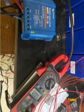

Screenshot 2021-12-07 121248.jpg
 
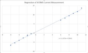
For further info - This is a linear regression of the measured current (X axis) against the 'moving average' of the current displayed by the unit (Y axis). It looks like there is both a gain and an offset error.

Screenshot 2021-12-08 163748.jpg
 
Seems too simple but the first thing I would do is clean and re-torque ALL connections.
 
It is. All voltages are accurate. I suspect either the shunt (if it indeed uses a shunt) is too large for the current or the ADC is to low precision or both - that explains the big current variations - ie quantisation error.

As for the scale and offset error, I suspect this is likely a factory calibration problem, best fixed by a system like JBD's where you calibrate at a certain charge current, then at a certain discharge current, and the software in the BMS calculates a transfer function. Present software only allows one point calibration.
 
Last edited:
I've found the following video that appears to show a series of 5 shunts on each side of the board. I'm thinking I may try removing some of the shunts and see if this provides better precision at the low amperages I intend to use this board at, and also proportionally remove the offset error. I wish I could understand german :)

 
@Synopsis:
BavarianSuperGuy is speaking a "bavarian"-german (dialect). In the video he is wondering about the orange copperwires between the Thyristors and worries what can happen, if there is a contact to the base . It seems for him, that they have forgotten some wires :) He has optimeized the cable route, so that he got the maximum of distance to the Thyrisors. Later he is talking about problems to get contact via RS485. He receives always a lot of "nullen" (0) with his terminal programm. So he is checking the conductor tracks from the ports to the chip. At first is shown the optical isolator-chip regarding RS485 and than he determine that the optical isolator chip for CAN is not mounted (forgotten??)
Another bad thing is, that the cooling stripes are to short ( only 5.5 cm/ not long enough ) and one of the thyristors is complet "nacked" ( without cooling stripe).
 
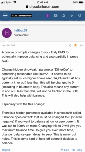
I have an issue with a DALY 4s 250 amp smart BMS, it will not register below about 3 amps. Of course this throws off the SOC. I have heard there is a setting that you can change in the PC software to lower the threshold.

Unfortunately I have been trying to get the PC to communicate with the BMS with no success, went around and around with DALY. I wonder if this could be a similar issue.


I realize they are different manufacturers but they probably have similar settings, below is what I found.
 

Attachments

  • 269093E3-2AD8-46B7-97FC-58A195DF372D.png
    269093E3-2AD8-46B7-97FC-58A195DF372D.png
    996.2 KB · Views: 6
Last edited:
No you are correct, the amps go all over the place. They say caused by the inverter making the some wave AC
 
@Synopsis:
BavarianSuperGuy is speaking a "bavarian"-german (dialect). In the video he is wondering about the orange copperwires between the Thyristors and worries what can happen, if there is a contact to the base . It seems for him, that they have forgotten some wires :) He has optimeized the cable route, so that he got the maximum of distance to the Thyrisors. Later he is talking about problems to get contact via RS485. He receives always a lot of "nullen" (0) with his terminal programm. So he is checking the conductor tracks from the ports to the chip. At first is shown the optical isolator-chip regarding RS485 and than he determine that the optical isolator chip for CAN is not mounted (forgotten??)
Another bad thing is, that the cooling stripes are to short ( only 5.5 cm/ not long enough ) and one of the thyristors is complet "nacked" ( without cooling stripe).

Yeah, saw that video and he's biased.

- That one mosfet that isn't under the thermal strip isn't used in the regular power control, in other words, it doesn't carry the current that the BMS switches. I don't remember exactly what it was for, but not switching the main current.
- They haven't forgotten any traces; those wires are fine to use to e.g. limit the amount of layers on the board. The lower current versions don't have them. The wires are insulated.
- At full 200A current, the total amount of heat dissipated by all mosfets together is 13W. Calculation:
Rds_on = 3.2mR typical at 25C. We have 10 pairs on the top and 10 pairs at the bottom. These are configured back to back, gives 6.4mR per pair at 25C. These 20 back to back pairs give a resistance of 6.4/20 = 0.32mR. Heating occurring at 200A continuous, P = R I^2 = 12.8W.
- The above won't cause the insulation to melt on those wires, and the BMS has overtemp protection on the MOSFETs in case something goes wrong; the insulation won't melt.
- Some versions don't support CAN and have the chip not mounted.
- Some versions, depending on where you buy them, have custom firmware which doesn't support the common RS485 protocol. It depends on where you but them since there are quite a few very cheap version on Aliexpress that work perfectly fine with the mobile app, but the RS485 protocol is completely different.
 
Last edited:
What I'm finding is that the current measurement is completely all over the place at low currents

Yes, the chip is inaccurate at low currents. JK knows about it (and they also know about the 'jumping' current display with an inverter, which only affect the app). Personally through, I've found them accurate enough for my purposes. It resets the capacity when the battery is fully charged, and gives a pretty good idea in day to day use of the remaining capacity, and averages out close enough. It's not accurate like a dedicated shunt, but does well at higher currents and properly protects against over-current. My guess is that JK is working on it, and should have a better one in a future version. I have a later model coming, hopefully this week (which is one that has a display interface) - I'll run some tests on that one, and open it up of course.
 
No you are correct, the amps go all over the place. They say caused by the inverter making the some wave AC
Thanks farmgirl - in my case I suspected it might be high ripple, so I turned the inverter off altogether. It made very little or no difference, in my case.
 
Yes, the chip is inaccurate at low currents. JK knows about it (and they also know about the 'jumping' current display with an inverter, which only affect the app). Personally through, I've found them accurate enough for my purposes. It resets the capacity when the battery is fully charged, and gives a pretty good idea in day to day use of the remaining capacity, and averages out close enough. It's not accurate like a dedicated shunt, but does well at higher currents and properly protects against over-current. My guess is that JK is working on it, and should have a better one in a future version. I have a later model coming, hopefully this week (which is one that has a display interface) - I'll run some tests on that one, and open it up of course.
Hi UpnorthandPersonal - thanks very much for all your extra detail - much appreciated! My version is relatively new - late december, and also has the external display.
 
@Synopsis:
BavarianSuperGuy is speaking a "bavarian"-german (dialect). In the video he is wondering about the orange copperwires between the Thyristors and worries what can happen, if there is a contact to the base . It seems for him, that they have forgotten some wires :) He has optimeized the cable route, so that he got the maximum of distance to the Thyrisors. Later he is talking about problems to get contact via RS485. He receives always a lot of "nullen" (0) with his terminal programm. So he is checking the conductor tracks from the ports to the chip. At first is shown the optical isolator-chip regarding RS485 and than he determine that the optical isolator chip for CAN is not mounted (forgotten??)
Another bad thing is, that the cooling stripes are to short ( only 5.5 cm/ not long enough ) and one of the thyristors is complet "nacked" ( without cooling stripe).
Andreas - thanks mate! That is really awesome information and I deeply appreciate your translation! I'd tried youtube subtitles and they were crap, so I tried carious other online translators and they were also crap - Bavarian dialect obviously confusing them :) so your translation is really appreciated -
 
Yes, the chip is inaccurate at low currents. JK knows about it (and they also know about the 'jumping' current display with an inverter, which only affect the app). Personally through, I've found them accurate enough for my purposes. It resets the capacity when the battery is fully charged, and gives a pretty good idea in day to day use of the remaining capacity, and averages out close enough. It's not accurate like a dedicated shunt, but does well at higher currents and properly protects against over-current. My guess is that JK is working on it, and should have a better one in a future version. I have a later model coming, hopefully this week (which is one that has a display interface) - I'll run some tests on that one, and open it up of course.

So it's a hardware and not a software issue? Mine jumps around plenty and continuously even during charge while my Midnite charge controller shows nice stable current. I sure would like to have an accurate reading at very low currents to see my idle loads. My magnum inverter has a shunt of it's own but drops off below 2 amps. The BMS should be accurate as well. I hate to add another. Running V3.7.5 of the APP until they get Android 12 figured out
 
So it's a hardware and not a software issue? Mine jumps around plenty and continuously even during charge while my Midnite charge controller shows nice stable current. I sure would like to have an accurate reading at very low currents to see my idle loads. My magnum inverter has a shunt of it's own but drops off below 2 amps. The BMS should be accurate as well. I hate to add another. Running V3.7.5 of the APP until they get Android 12 figured out

It's a bit of both. I can't quickly summarize right now, but check this thread starting at the post linked:

 
Back
Top