Hey guys,
New here! I have been researching for a couple months (new to solar and battery tech), and am planning a solar system for a shed/yard lighting, and was thinking about ordering 2 of the 4 packs to make a 24v battery.
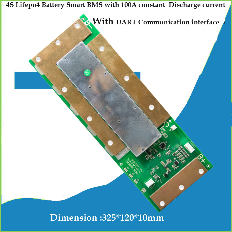
For this, would I just use a Daly 8s 24v bms? What do I use to top balance?
Waiting on solar kit from Santan solar with 3 additional panels for 1500w pv in total. And reliable 3000w 24v inverter.
I'd like to keep whole setup under 2k, but like stated above, not sure how to build 24v battery with the battery hookup 4pack banks.
New here! I have been researching for a couple months (new to solar and battery tech), and am planning a solar system for a shed/yard lighting, and was thinking about ordering 2 of the 4 packs to make a 24v battery.
For this, would I just use a Daly 8s 24v bms? What do I use to top balance?
Waiting on solar kit from Santan solar with 3 additional panels for 1500w pv in total. And reliable 3000w 24v inverter.
I'd like to keep whole setup under 2k, but like stated above, not sure how to build 24v battery with the battery hookup 4pack banks.


") WIll be top balancing this week.
WIll be top balancing this week.