diy solar

diy solar

laying out pcb for inrush limiter

Roswell Bob

Solar Enthusiast
Joined
Dec 5, 2020
Messages
759
Location
Warner, NH
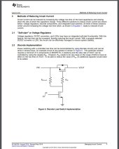
I am laying out a simple board for inrush limiter. Board is automatic so that BMS never has to start into an empty capacitor bank. While charge resistor will be on board there will be connections for an external contactor for the main current. There is also hooks for an external on/off switch. Turn switch off and voltage is removed from inverter. If anybody want board let me know with pvt. msg.
 
there will be connections for an external contactor for the main current.
Is this a general use item or is it specifically for use between a BMS and an inverter?
Will it support 12V and 24V contractors? (not sure i want yet another contactor to keep powered...)
 
It can be used without a bms. The reason for my doing this board is to keep inrush current under control to prevent BMS damage or fuse clearing. I am leaving lead-acid for LiFePO4. It will be able to run any voltage system.
 
Have you considered a transistorized solution such as that shown in the attached picture? It would obviate the expensive contactor, but I don't know if the required transistors would be more expensive or effective when considering the currents in play.
 

Attachments

  • inrush limiting.jpg
    inrush limiting.jpg
    178.3 KB · Views: 23
Have you considered a transistorized solution such as that shown in the attached picture? It would obviate the expensive contactor, but I don't know if the required transistors would be more expensive or effective when considering the currents in play.
Yes, I am aware of the transistor solution. I have used it in the past. It is fairly straightforward to get it dialed in, but not so simple as a contactor solution. I watched one of my coworkers smoke a very expensive (custom) transistor module trying to get his implementation working. I will stick with contactor solution. Here is a low cost contactor that might work fine. https://www.digikey.com/en/products/detail/AEV250-GAN/2040-AEV250-GAN-ND/14119839?itemSeq=387394181
 
What are the performance specifications you're trying to achieve?
Any voltage system 12/24/48...
This goes between BMS and inverter.
Automatic - If BMS drops out and comes back on there is limiting to protect BMS and Fuse.
Two wire control. A contact closure initiates cycle and opening contact removes power.
External contactor so only signal wires to board. Contactor could be replaced with FET or SSR
Simple dual comparator circuit. First comparator determines when caps charged to near 90% - second comparator provides another second or so of wait.
Inrush limiter is probably PTC or NTC thermister. NTC would need an additional fuse.
Through hole construction????? SMT?????
3"x5" max size.
Layout in Altium with silkscreen and soldermask. I have recently purchased Altium Designer license so am in learning mode.
 
cool!!

interesting use of comparator??

following with interest, idea has merit imho!

having an "auto boot sequence" with precharge like this is appealing to me for reliability and ease of operation (ease of operation = can do it without coffee ;))

even with confidence in MOSFET BMS, i still plan on using a contactor. also want precharge and single button safe boot and shutdown

super appealing concept!

?
 
I'm curious. Are you people connecting/disconnecting power to the inverter often? Is this only in a residential system?

In the last three months I've only connected power to my 3kw inverter once when I first tied it into the system. I used a resistor and a couple of clip leads to pre-charge it and since then it's remained connect to the batteries.
 
ease of use is a major reason for me

turning one single switch, which automates the precharge and then close contactor when ready, that appeals to me

not expecting to do it frequently, but when it is needed, if it could happen automatically that would make operation simpler for me
 
I turn my inverter on and off using the remote switch but that doesn't disconnect the DC input. If my BMS disconnects on the discharge side then something is really wrong as my batteries never get that low
 
I have the layout for inrush limiter complete. There is about $10 in parts not including the PCB. If anyone is interested in putting one of these together let me know. I can supply a board or a near complete set of parts. I will put a package together this week and post it.
 
Here is board. If anyone is interested in a board then get with me. I am not quite sure of price until I know of anyone else wants one. I have a circuit description I will post a little bit later. I have errands to run for now. If anyone want to spend an hour or so to critique then I will discount cost of board. I had to convert word doc to pdf in order to upload.
 

Attachments

  • inrush.pdf
    312.1 KB · Views: 22
  • Inrush Limiter Theory of Operation.pdf
    74.4 KB · Views: 16
Last edited:
there are solid state contactors now that can just handle the raw power, no inrush current mangement circuitry needed
 
Back
Top