diy solar

diy solar

laying out pcb for inrush limiter

there are solid state contactors now that can just handle the raw power, no inrush current mangement circuitry needed
Inrush current will occur when you use any kind of switching device to apply power to capacitors.
Do you have the link for one?
Power dissipation spec and full load?
Inrush current spec?
Etc.......
 
They can handle 20,000A?

I would think, either they need to have a soft-start (precharge) function, or they will blow your class-T fuse.
 
They can handle 20,000A?

I would think, either they need to have a soft-start (precharge) function, or they will blow your class-T fuse.
20kA for 1-10ms is feasible, just crazily expensive. To actually reduce inrush with FETS you can try to use their ohmic property. It's extreme risk, and I would only try it with an unlimited budget lol.
 
Inrush current will occur when you use any kind of switching device to apply power to capacitors.
Do you have the link for one?
Power dissipation spec and full load?
Inrush current spec?
Etc.......
Nah don't try limit inrush current by using MOSFETS as resistors. It's a bad suggestion, possible but not practical lol
 
Thinking out loud. BMS is last line of defence so if it trips there is something wrong. Inverter should trip out before BMS and caps will stay charged. If the BMS has tripped I don't know if I'd want anything automatic causing issues.
 
Nah don't try limit inrush current by using MOSFETS as resistors. It's a bad suggestion, possible but not practical lol
Well, that is why I ask why you suggesting using SS contactor, I know it is not practical using the simple MOSFET based SS contactor device, lol.
 
Nah don't try limit inrush current by using MOSFETS as resistors. It's a bad suggestion, possible but not practical lol

Very common, actually. Just a charge pump to gradually raise gate voltage, turn it on slowly. It works fine so long as load doesn't get impatient.


Commonly available ICs drive two back-to-back MOSFETs, handle reverse polarity, optionally wait long enough that AC if applied doesn't enable them.

We burned out plenty of FETs because other boards weren't designed with soft-start input in mind.
 
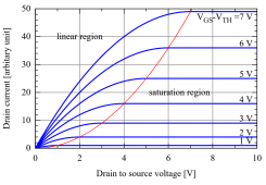
MOSFET are not only "on" and "off"

in between "on" and "off" is a variable resistor of sorts, and that could be a pre-charge circuit (surge suppression circuit)

fine grained control circuit seems important for this.

for more crude form, connecting an external resistor can work too. but it requires another component.
 
I recently did a 1000A/600V solid state DC breaker for a client. I used a fet to do inrush. It is actually quite easy. The gate voltage is controlled through a stiff source. The drain current through the fet is controlled as a function of the voltage across it and the heatsink temperature. What is being controlled is the junction temperature of the fet Tj={Vds x Id) x Rtheata (j-c)}+Tsink. So by controlling Id we can control Tj.
 
Last edited:
Back
Top