diy solar

diy solar

Building the sickest ® VAWT ever. Brilliant minds unite please!!

in the current plans the blades are static. I might consider plain vertical lift blades. the same profile as I have now but then not helix as I think I will have difficulties finding a 3d printer to print a resin mold for the carbon fiber when it is helix shape.
 
Guy wires from top of pole would make it pretty secure.
The higher the better. Go ahead and start near ground, but later use a tilt-up tower. Guy the tower from just below rotor as well.

These turbines use their blades for lift, just like horizontal ones, to turbulence would kill performance.
It may be practical to make a 10m tower, but that will still see lots of turbulence. It probably would be much better 30m tall.

Remember a braking mechanism as well. Electrical short should work up to some wind speed. Mechanical hard stop could help in higher winds. Tilt-down before they hit would be good too.
 
Can anyone please give some pointers regarding how to create a test rig for the alternator?

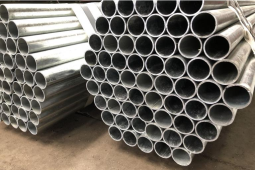
I believe the central column of the turbine should be round with a large diameter. Something like this
1638209239629.png

But for the life of me I can't find a ball bearing large enough to carry the rotor.
 
Ahh no the stators should have a ball bearing of some kind and the rotor should be directly connected to the column.
I am planning to have 2 x stator disk with 3 phases each. So the stators will be sandwiching the rotor.
But still how to do it.
 
Consider tapered roller, to support vertical load.
There are probably some around 3.5" inside diameter.

For first prototype, you could start with bearings you can scrounge, e.g. wrecking hard parts.
Scale the turbine to fit what is economical and available.

I think RPM will be fairly low. You may want belt/chain drive to spin an alternator faster.
You're trying to assemble magnets and wind or otherwise "roll your own".
That might be best save for final version, just connect an off-the-shelf generator or alternator to begin.

If you use an automotive alternator with slip rings, then instead of charge controller varying drag on turbine, you can use a DC source exciting armature to vary the load. You can exercise its range, map out performance vs. windspeed. Put an anemometer on the tower too.
 
probably a (really) bad idea, but linear actuator skeleton to expand in low wind? probably not a good idea to have an active system that could fail in the extended position with worm gears holding it in place.. random thinking
 
probably a (really) bad idea, but linear actuator skeleton to expand in low wind? probably not a good idea to have an active system that could fail in the extended position with worm gears holding it in place.. random thinking
all thoughts are welcome. But I am probably not able to make that :)
 
Flexible blades, curved out to make almost spherical shape. Cable pulls down on lower bearing to draw it in.
Sheets to the Wind!

Actually, if straight blades are hinged in the middle, fully extended would reduce swept area to zero. Much like turning HWAT crosswise to the wind.
That gets away from fully extended by G forces being worst situation.
 
A different kind of wind generator made from old 50 gallon drums and axle bearings!

Oh, better for thrust/propulsion than generation while in a fixed location. So OP could use three spinning cylinders instead of blades.
Amazing that works at all (returns more energy than you spend spinning them.) Hmm, could they be spun by their own small blades?
 
I am trying to get more attention to this, self judged, well important thread with call for arms
Hopefully it will help with the following issues I encounter
 
Current issue is that I am unable to print out a full scale quarter of the alternator using an A4 printer.
Sure the adobe pdf viewer has a poster print option in where it cuts a large A0 source into A4 pieces but it leads no where.

Always misalignment even though printing border-less.

1638369854561.png
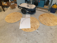
What you see here is 3 disks with 82cm diameter. 2 of them are for the stators (3 phase coils on each of them). 1 below and one above the rotor.
As I can't seem to find any bearings that can deal with this scale I think I need to 3d print them.
(roller bearings part somewhere in the middle)

I call for advice from people that know about 3d printing / cnc milling to aid in getting this show on the road
 
I suggest you fabricate a prototype that fits your equipment.

I spent 3 years of high school metal shop and summer school at the J.C. trying to fabricate a rather large metal cutting lathe. I cut a few gears, made the compound feed with acme screw and tapered adjustment for play in its bevel ways, and made the 360 degree rotating component it mounts on.

Maybe if I had build something like a jeweler's lathe I would have finished.

A few years later I bought a used 9" South Bend for $500.
For the turbine I do plan to not go full scale from the get go. But boy even the price for a single 3d print at 10% for one straight blade will cost me like 40 euro's So I am really thinking hard on how to combat that issue.

I think I have a solution and will share that a bit later on.

Now for the alternator I do not believe I can prototype with a scaled down version. Or at least I do not have the math skills to do so. No for the alternator it's full size or nothing from my vantage point at the moment.
 
Do you want to focus on VWAT turbine, or on alternator?

If the turbine, make a guyed tower out of pipe/conduit. Get a pair of bearings to fit over it, and fabricate mounts for inner races that clamp to the tower. Mounts for outer races that fit a larger pipe; that is the rotating hub of the turbine.

Make it belt or chain drive to an automotive alternator. Excite the alternator with an external DC supply, and you can vary load for any RPM.
 
For the turbine I do plan to not go full scale from the get go. But boy even the price for a single 3d print at 10% for one straight blade will cost me like 40 euro's So I am really thinking hard on how to combat that issue.

You could sand a strip of Styrofoam to shape, then wrap in fiberglass.
You could print ribs and join them with truss work, then wrap a skin over it. It would look like an early airplane wing, perhaps with fabric and dope. or sheet material bonded on.
 
It's difficult to make a choice where to focus on. I mean when I wait for components for the alternator I spend time modeling a turbine. When I wait for information regarding a 3d printer for printing a turbine blade I spend time on the alternator.

Choices choices. Sooo much to do :(

I'd like to keep the ball rolling and spend my time on all aspects in parallel if possible
 
Back
Top