diy solar

diy solar

LFP 126 amp-hour house battery design and build for a class A RV.

JohnJayMack

New Member
Joined
Dec 22, 2020
Messages
25
I made a decision several months ago to investigate and build a 12 volt 100ah sized battery for an RV. I was recovering from shoulder surgery and had plenty of time on my hands. After completing my first build, I decided to document what I had done. I am going to split this project into a series of posts. Also, since this was done for my pleasure, I am including the actual document as an attachment so that those who wish to read it fully can do so, and those who are just browsing are not forced into a TL::DR paper that they really do not wish to read. I hope that this is as enjoyable to others as it has been to me.

The short version of the attachedBattery.jpg document goes as follows: RV house batteries are important, AGM lead acid batteries are heavy and old technology, commercial LFP batteries have limited physical sizes and capacity options, commercial LFP batteries are expensive, and building a battery to meet my needs is personally satisfying.

This is section 1 of several.

Jay
 

Attachments

  • Battery Project Section 1.pdf
    80.3 KB · Views: 18
I like the looks of that batt lid? Not keen on downloading a pdf. Any chances on posting more?
 
This posts covers some of my research and tools that I used. The attached pdf has the complete8 page document and the attached spreadsheet is the one I use to do my battery design.

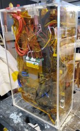
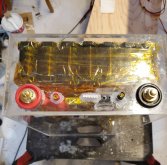
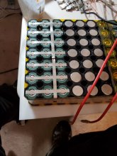
This is the first large battery that I have built. It has tested out at around 135 Ah and supplied 110 amps for over an hour without any noticeable heating.
CamScanner 12-26-2020 11.33_30.jpgCamScanner 12-26-2020 11.33_28.jpg
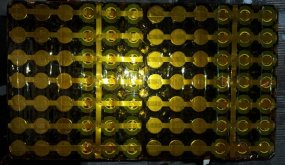
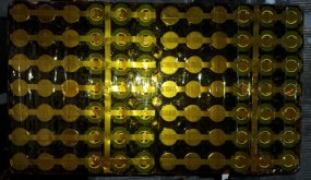
This battery is described as a 21P4S battery. Each cell used is a 6000 mAh cell giving a calculated rating of 126 Ah. If I had used prismatic cells, the battery would have been described as a 1P4S battery. The battery description does not fully describe that battery size.

When doing your online research, you can find many different authors and many different opinions. I bookmark site that I have gone to and authors who present information in a thorough manner and put the bookmarks into a folder system associated with Chrome. In this manner I can go back and review the different points of view and information provided.

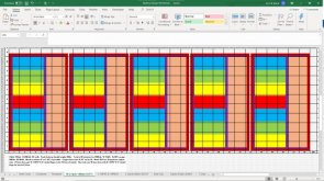
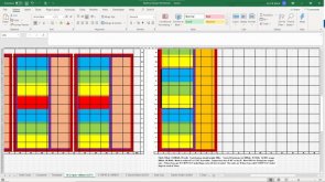
I use a spreadsheet program to draw my possible batteries to scale.

21P4S Battery Build plan.jpg
21P4S Battery Build vertical.jpg
I did various designs to see what size and shape batteries would fit into the space that I have. Different arrangements have different physical dimensions and designing a battery that is too large means it won't fit, and too small wastes space.

Once I decided on a design, I considered how much current would be carried by the internal conductors. The battery I built has 7 columns with 12 cells in each column. In each column, 3 cells compose a section and therefore determine the possible current. The cells I used have a 1C continuous rating of 6 amps, a 3C continuous rating of 18 amps, and a 10C for 10 seconds rating of 60 amps. I decided to design for a minimum current capability of 18 amps.

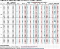
In looking at the current carrying capabilities of nickel strips, I came across two ampacity charts. This first chart indicated that 0.2mm by 8mm nickel strips are rated for 6.4 amps and 0.3mm by 8mm strips are rated for 9.4 amps. Further research turned up a second sheet by the same author.
Ampacity (Powestream extrapolation)1.jpg

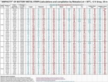
This second sheet was done for lower temperature rise and less voltage drops. Since I do not want the battery to heat internally during use, and any voltage drop is to be avoided, I check for the new current ratings. 0.2mm by 8mm strips are now rated for 2.4 amps and 0.3mm by 8mm strips are rated for 3.2 amps. These lower ratings would require a stack of 0.3mm strips of at least 6 strips per connection, a quantity I believe to be too many.
Ampacity (10 meter - Low temp)1.jpg
I decided that the main current conductors should be copper. There is more detail in the attached pdf for those that are interested.

Jay
 

Attachments

  • Battery Project Section Two.pdf
    1.1 MB · Views: 5
Jay,

I found your build thread!

I think simple to own and support. I make my living in root cause analysis when something fails [irony huh]

I have toyed with the using the BH 32650 for my large banks and I talked myself out of it, my rationale was:
1. Points of failure - every weld can be a point of failure, hot point.
2. Packaging cells - I love your plexi design, but I was not sure what to use to keep so many cells together
3. Volume/Capacity - The sheer volume vs capacity was a great reason I went with the 280AH cells.
4. Overall capacity and debugging down the road - have 12 large cells it is simpler to find a bad apple and toss it vs living with reduced capacity cuz of bad cells.

One thing I reluctant to do go with a large bank as your with a product with little track record. I would hedge my bets and go 50/50, 50 bank of 32650 and 50% 280 AH cells or winstons.

Unfortunately, when it comes to stuff failing it is not if, it is when.

I am going over your build docs...
 
I look forward to your analysis. A little of my background. I am an Elevator Mechanic. I began as a Field Engineer in 1981. Your last statement, "Unfortunately, when it comes to stuff failing it is not if, it is when" is a statement that I have seen proven over and over again for 40 years! And I agree with that statement 200%.

I will be posting today or tomorrow more on my last build. It should help address points 1 & 2. And it can surely give some information/opinions/thoughts as to the pros and cons.

Points #3 #4 are why I chose the directions I have taken. Once again, subject to discussion/opinions/thoughts.

For point #3, I did look at the large prismatic cells. They are very interesting and attractive for the reasons that you mentioned. My decision was based on two perspectives. The first is their size. I have a specific volume of space that I am trying to use to the best advantage. I have found through out my life that many people only look at the area that they have to use. They do not look at the height of their space. Sometimes this lack of awareness of the height of the area is because the devices that they want to put into the area comes in a standard height--no options or choices. When I looked at the area that I had available, I was looking at not fitting into the area footprint, but also making maximum use of the of the area above the battery compartment.

My thoughts on point #4 and the un-numbered comment are as follows. I watched several videos on various builds using various cells. One of the brand names in commercial lithium batteries apparently use the 32650 cells for their 100Ah batteries. I also watched and listened to different opinions and suggestions regarding battery cells. Will Prowse suggested the LFP prismatic cells for many very positive reasons. Once again, the size of the prismatic cells limited their use in certain spaces.

I actually decided to go down the path I chose is for flexibility and redundancy. The battery size is working out to be approximately 10-3/8" x 17-3/4" x 5-1/2". The terminals are on the 17-3/4" side and included in the dimension given. I can fit a total of 10 batteries of these dimensions into the space available. Each battery is rated at 126Ah giving me a possible total of 1260 Ah. The space I am using, and the traditional standard that I am designing against is four sets of two 6-volt 220Ah AGM batteries giving a manufacturers rating of 660Ah. Using the 50% rule for AGM batteries as a target point, which is 330AH, and using 70% usability for the Lithium technology, I need 4 of my batteries to provide 352Ah which meets and exceeds the AGM target. I have space for 10. If I build 6 batteries, I have 529AH available.

Looking at one failure mode, if I lose 1 AGM 6-volt battery, I have lost 1/4 of my capacity, from 330Ah down to 248Ah. If I only build and use 4 LFP batteries, I drop from 352Ah to 264Ah. I am still above my AGM reference.

Finally, I have been looking at the efficiency of 24 volt and 48 volt inverters. my having the ability to reconfigure 12 volt batteries to 24, 36, or 48 volt outputs is an option.

I hope and look forward to your thoughts. Strong debate and sharing of differing opinions best serves to raise the knowledge of all.

Jay
 
Jay

Comparing volume and Ah capacity of 32650 [6000mAh] vs EVE 280 Cells,

Can you pls eyeball my calc,

10-3/8" x 17-3/4" x 5-1/2" =

1012.8594​
in3
126Ah/1012.85 = 0.124 Ah/in3 @12 V

FYI: 1 32650 6000mAh cell is 3.44 inch3

mAh per cubic inch:

1 BH Cell:
6000/3.44 = 1744.2 mAh/inch3


1 EVE 280Ah cell has a volume of 12.61 inch3 @ 3.3 volts

280000/12.61 = 22204.6 mAh/inch3

One EVE cell has 12.7 times the energy density of 1 BH 32650 cell??
 
Jay,
Can you tell us a bit more about your power needs on the RV please.
 
I think that we need to state some dimensions to be ale to verify calculations. Sometimes different assumption lead to different figure which leads to pointless conversations.

The 32650 cells measure 1.25 dia by 2.75 tall. This gives me a volume of 3.37 cu-in. We are close to agreement. However, I would suggest that a more realistic volume measurement would include the actual volume required. When I put the Cell holders on the cell, the dimensions increase to 1.375" by 1.375" by 2.75" giving a volume of 5.2 cu-in. Based on these numbers, the energy density would be 6000mAh/5.2cu-in=1153.8mAh/cu-in. My numbers make the 32650 look worse.

I went on EVE Energy North website and looked for a LFP battery rated at 280Ah. The listed dimensions for the battery that I found are 205mm height by 173.6mm width by 72mm thick. Using 25.4mm/inch as a conversion factor, I get 205/25.4=8.1" height by 173.6/25.4=6.8" wide by 72/25.4=2.8" thick. This gives me a volume of 154.2 cu-in. My volume is in major disagreement with yours. If my volume calculation is correct, then 280000mAh/154.2 cu-in = 1815.8mAh/cu=in. The EVE cell is still more energy dense, but the advantage is more like 1815.8/1153.2=1.57 to 1. All of the above is based on my assumptions and my math both of which should be checked.

The RV is all electric. With the exception of diesel for the main engine, the generator, and the furnace, everything else is electric. Our plans involve not being tied to a parking space with 50 amp service. Many 30 amp services cannot supply enough power to run AC in summer when it is hot, and some places provide no hookups at all. And running a generator consumes diesel and noise. The more usable amp hours that you have, the longer that you can operate with running an engine. Energy needs are always a balance of how you want to live, what creature comforts you want or feel you need, what energy you can store for when you are not connected, and how you can replenish the energy you use.

When driving down the road, you have alternator power available, but you must be careful that you do not burn up your alternator. Solar can provide replenishment when the sun shine, but parking in the shade keeps things naturally cooler. And a rainy day severely reduces solar production. Running a generator is noisy and consumes fuel.. And in some areas, running the generator between certain hours is discourteous to others at a minimum and prohibited in many places.

BTW, I installed 60 - 285 watt solar panels broken into 4 strings feeding two Solar Edge10kw inverters. My I designed the system with a lot of help and support from my vendor, and my wife and I installed the system. I wired the system to the inverters and replace my main panel and then made the connections. I got my inspections completed and turned on my system in February 2016 three days before my left shoulder rotator cuff surgery.

Today's numbers are 35.21kWh generated, for the month 128.92 kWh and for the lifetime 122.79 MWh. I believe in solar. I own my system and since I did it myself, my cost was comparable to quotes that I had received for 20 panel installs.

Jay
 
Last edited:
60 - 285 watt panels, ?, wow, impressive!

I have a 33ft holiday rambler tow behind and you absolutely correct, 30A/50A service spots are spoken for well in advance.

I will breakdown the topics:

Alternator charging - I am looking into this, both my diesel chevy and ford 3.5 TT have HD alternator with mucho amps on paper.
Can one limit amount of amps that is drawn off the alternator? In your solution, Solar Edge, can you customize the charging AMPs/Volts?
 
I think that I forgot to add the words" to my house" when I mentioned my solar install. My bad if I caused a misunderstanding. The Installation described is a grid tie system on my home. This means that if the commercial power supply goes off line, my system shuts down. I am pretty sure that a grid tie system would not be appropriate for an off the grid situation.

As I understand the Solar Edge system, each panel is connected to power optimizer module at the panel. The optimizers communicate with each other and the Solar Edge inverter in a manner that I barely understand. What I was told is that the system automatically adjusts the output of each module so that the string voltage stays at about 350 volts. Also, the modules can adapt automatically to a bad module/panel, a shaded panel, and multiple strings in parallel. I have looked at the system at various times during the solar day and the system voltage stays pretty constant. The power reported in watts is the variable until sunset.

For alternator charging, I believe that you should look for a Buck-Boost DC-DC converter. I have not completed my research but my initial impression is that may work. Also, I have read that the rated output of the alternator must be known and respected or you may burn up the alternator.
 
Jay, I wanted to PM ya, but this forum does not seem to have PM feature.

That is quite a massive and impressive solar installation you have at home.

What is your projected max consumption on the rv?
What is your projected max charging plan and how?

Alternator - I had to dig up the uplifter's guide for my van to find the alternator output/rpm graph. based on that I need raised idle enabled in the ecu and have a switch to trigger it.

[fyi, I posted this reply before and seems to have not gone through]
 
With regards to my solar build, maybe some background will explain my thought processes and decisions. Some are interested in history and points of view, others may just want to skip to the conclusions.

In the 70s I had a converted van that I used to camp in at times. The deep cycle battery for lights and a small refrigerator and the main battery for engine start were both charged off of the alternator. I had a battery isolation solenoid that connected the deep cycle to the charging system when the engine was running. The overall system did work, sort of, but energy storage was minimal, and the battery life was measured in months.

In the late 80s and early 90s, I actively looked at outfitting a cruising sailboat and going full time cruising. I read and studied a book called
"Living on 12 Volts With Ample Power". I had big plans but family circumstances put an end to those plans.

About ten years back, one of our neighbor had solar put up on their roof. We saw the advantages and got a quote for an install. The quoted cost put what the company proposed out of reach, and the offset was very limited. It also appeared to me that the company was looking over their should as to where we had come from and forecasting that this would be the future. I had a different point of view.

Does anyone believe that there will be greater need for electricity in the future? Does anyone think that centralized generation of power using fossil fuels is the best solution to increased power need? Are electric cars going to disappear from society because they are a fad?

I looked at and designed my system round the concept that what I build today will be small tomorrow. I also looked at reducing my fossil fuel footprint as much as I could.

I found a company that worked closely with the DIY crowd. They had many products for sale but they also were available to answer questions and help with designs. I also contacted the Inspection Department in my city. One of their inspectors actually came to my home and pointed out issues that I have to address that I had not even thought about. And his visit was FREE because our city supports solar.

The choice of sixty panel install came because of full pallet discounts that I took advantage of. I had the advantage of having done construction and was able to do all of the installation. Because my roof was old and needed replacement, I coordinated the replacement of the roof with the installation of my solar mounting rack supports. I had done a layout of where the supports should be placed and was able to have the supports flashed in without damaging the roof.

The cost of my install of 60 panels was approximately the same as the quoted cost of 24 panel by a solar company. ?

My plan has left room for 5 additional panels if needed for future growth of the system. After the install, we began a process of converting to all electric. When we need to replace the washer and dryer, the dryer became electric. When the hot water heater needed to be replaced, we went with a reversal cycle all electric water heater. When the house HVAC died, we upgraded to mostly all electric heating and cooling with gas heating as a backup if the outside temperature was too low.

All on that subject for now.

Jay
 
My projected charging plan is to look for every opportunity to add to the battery charge as well as looking what and where we expend energy. In my youth, I carried tents and canoes in the Quetico / Superior parks and thoroughly enjoyed myself. I also canoed and camped on the Spring River and the Eleven Point River in Arkansas, and hiked in the Smokie Mountains in Tennessee, the Green Mountains in Vermont, and the White Mountains of New Hampshire. Now I want my creature comforts. I am not interested in 'Roughing It.' My wife and I enjoy our genealogical research, and my wife likes to quilt while I am outside trying to improve my marksmanship. I also firmly believe that there are more than 300 million in our beautiful country that I have not met, and Most of them are really fine people. We hope to see as much of the country as is possible, to get to know the smaller, more out of the way places, and if, by chance, we find ourselves with bad neighbors one night, we shall simply start the engine the next morning and, with a smile, wave goodbye.

Whenever the main engine is in operation, whatever excess power that might be available from the alternator should be flowing into the bank. I do not know if I can mount a second alternator on the main engine, but I am investigating the possibilities.

I am looking at permanently mounting as many solar panel as is possible on the roof. I am considering and can not rule out the possibility of additional portable panel and/or a system of double stacked panels that might be deployed when boondocking.

Using when needed, but minimizing the use of the generator is part of the plan. If driving from one full hookup park to another, I believe that the auxiliary generator would ever be needed. Of course, if travelling in some parts of the country during the summer, running the generator while driving to run the main air conditioners might or may be needed. The same might be said for staying in parks that only have 30 amp power service available.

And finally, anytime I can plug into the power grid, I intend to do so. 50 amps when available, next 30 amps, and a 110 household outlet if that is the only option.

Obviously changing the container from AGM to Lithium is a major part of the equation. The size of the storage capacity has both good and bad points. As you add capacity, you add cost, take up space, and add weight. With a given space, Lithium helps with energy density and weight. the Lithium technology also helps with useable capacity related to advertised capacity and helps with efficiency in recharging.
 
Battery Build Project Section Three Proof of concept.

I decided to build a smaller version of my final battery for testing, etc.

After briefly considering building my own welder, I decided to purchase a kWeld welder. I found it to be an excellent tool, but it does have its limits. I tried various ways to push it to weld my 0.3mm 8mm nickel plated copper. I was unsuccessful. I did blow the 300 amp fuse multiple times and may have stressed the welder to the breaking point. Any failure of the welder at this point is due solely to the abusive way in which I tried to stretch the welder's capabilities.

I decided that for the currents that I wanted from the battery, I would need to incorporate copper conductors into the build. To connect these copper conductors to the battery cells, I would have to use a nickel conductor bridge. The nickel bridge would be welded to the cell and soldered to the copper conductor.

This design does add complexity to the build and time, but I feel that the benefits out weigh the costs.

My small first battery is a 4P4S unit without a BMS. I charge it and monitor it using a iCharger X8.

Jay
 

Attachments

  • Section Three Proof of Concept.pdf
    361.1 KB · Views: 2
Battery Build Project Section Three Basic Layout and Assembly

For the first large battery, I have chosen a 21P4S flat assembly. This will use 84 cells, and give me a 126aH battery.
CamScanner 12-03-2020 16.29_2.jpg CamScanner 12-03-2020 16.29_4.jpgCamScanner 12-03-2020 16.29_6.jpg
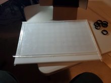
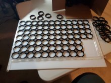
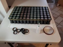
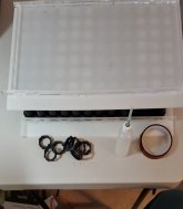
I purchased pieces two pieces of HDP 1/4" thick plastic and some 1/4" acrylic squares. I arranged the bottom cell holders on the plastic sheet. The perimeter of the cell holders was contained by the square acrylic pieces glued with hot melt glue to the HDP sheet. Once the cell holders are arranged with flat sides together and shoulder tabs down, the cells were solvent welded together.
CamScanner 12-03-2020 16.29_45.jpgCamScanner 12-03-2020 16.29_7.jpgCamScanner 12-03-2020 16.29_13.jpgCamScanner 12-03-2020 16.29_15.jpg
While the solvent welds are setting, I added insulation to the positive ends of the cells. This added insulation may not have been required, but I felt it was relatively inexpensive insurance against an internal short.

My next step was to add the cells to the holders. Three rows of seven each positive side up, three rows of negative up, and so on till all 84 cells are in place.

Next, put the top cell holders onto the cells making sure that the flats are together. Solvent weld the holders in place. After a period of time for the welds to take a preliminary set, wrap the top cell holders 2.5 times using 1/2" Kapton tape to support the welds and to add support to the assembly.
CamScanner 12-03-2020 16.29_16.jpgCamScanner 12-03-2020 16.29_22.jpg
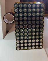
I used the second piece of HDP plastic on top of the cells to help keep the assembly together as I turned it over. I taped the bottom holders together with1/2" Kapton tape. Now I could tape the cells together using 2" wide Kapton tape. This gives me a relatively solid unit to work with.

At this point I have 84 individual cells bound together in a rectangular form that measures approximately 16-7/8" tall by 9-7/8" wide by 2-7/8" deep. The next step is to make connections.
 

Attachments

  • Section 4 First 21P4S Basic Layout.pdf
    865.3 KB · Views: 1
Section 4
The First 21P4S Battery
Electrical Circuit Fundamentals and Laws


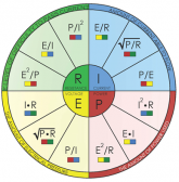
The construction of this 212P4S battery is a massive series/parallel circuit. And always the laws of electricity developed by Geog Ohm and Gustav Kirchhoff will apply. The two laws that every circuit designer should be familiar with are Ohm’s law – E=IxR and the Power law P=IxE. There is a nice pie chart that shows all the forms of these two laws.
1610656836604.png
The first design variable to establish is the voltage. I have chosen 12 volts for my battery design. At this point, I think it is important to note that saying that I am designing a 12-volt battery will not actually mean that the voltage will be 12 volts. The actual battery voltage will depend on battery chemistry and state of charge. Using a fix number at this point simplifies the conversation.

The next design criterion is the power available from the battery. In battery systems, we rate batteries in amp-hours, Ah, which is the unit that battery manufacturers use. I have decided to build a battery in the 100Ah range, and the actual battery that I am building is rated at 126Ah.

Now if I could get 126 amperes from this battery over a period of 1 hour at a voltage of 12 volts, then the power formula, P=ExI, shows me that the battery would produce 1512 watts for that hour or 1.5 kilowatt hours, or 1.5kwh.

So, will all the internal connections of the battery have to carry the full 126 amps? To answer this question, we must dig deeper into the actual battery structure.

Each of the 32650 LFP cells that I have used is rated at 6Ah. The cells are arranged such that only three cells of the same polarity are directly in the path of current flow. Therefore, each path of current flow will carry 18 amps. Since there are 7 paths of current flow, the 7 paths combine to give the battery 126 amps of current flow.

When we look closer at the cell specifications, we see that the cell can deliver 18 amps continuously, and 60 amps for as much as 10 seconds. What do we do to account for these larger values?

As part of the design, we will be incorporating a Battery Monitoring System, BMS, which can be programmed to give us some current limits. We can design for expected normal currents and use the BMS as a safety device.

Next, we look at the cell to cell connections. Our connections to each cell will be through spot welds. The best material that I have for spot welding is nickel, but nickel has a relatively high resistance. The best, commonly used connection material would be copper, but welding copper is not easy and requires much more heat. In the construction of the battery, we must limit the heat applied to the cells.

The amount of current that a conductor can carry without heating up is directly related to the internal resistance of the conductor. This internal resistance is related to the actual material of the conductor and the cross-sectional area of the conductor.

The heat dissipated in the internal conductors is typically called the loss. This a power loss, as heat, that does not benefit you. This heat can do damage to your battery by directly harming the cells themselves, and the heat can put stress on your welds.

My choice to address my concerns maybe unusual and does take more time to build, but I believe that will address my concerns.

First, I chose 0.3mm by 8mm tape for my direct to cell connections. I have found that I can successfully weld this tape to the cells. I then run parallel 12awg copper wire to carry the bulk of the current.

By getting the bulk of the current into the copper, I also reduce the loss in the battery. Also, by minimizing the heating in the conductor, I have minimized the thermal growth and the strain on the welds.

I first heard of the following initials and phrase from the author Robert Heinlein-TANSTAAFL which translates to ‘There Ain’t No Such Thing As A Free Lunch’. What I have built requires more time and many more welds. Time will tell if my decisions are wise.
 

Attachments

  • Section 4 The First 21P4S Battery Electrical Circuit Fundamentals and Laws.pdf
    221.8 KB · Views: 0
Initial Welded Connections and Top Balancing

Making the Initial Welded Connections and Top Balancing​


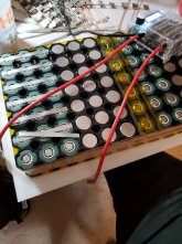
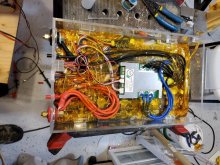
These two pictures show the initial connections made on the battery.

The strips that connect the positive ends of the cells are 0.3mm by 8mm nickel. At this point I am making connections to the positive point of the battery. In the second picture you see a 0.2mm by 8mm nickel tape connecting all the parallel cells together for balancing purposes.

CamScanner 12-03-2020 16.29_34.jpgCamScanner 12-03-2020 16.29_35.jpgIn this picture, the rest of the tapes have been added and the balancing connections have been made. Then the entire side is covered with insulating Kapton tape.
CamScanner 12-03-2020 16.29_46.jpgCamScanner 12-03-2020 16.29_47.jpg

In the upper section is the negative pole of the battery. In the middle section is the third most positive section relative to the negative section. In the bottom section is the fifth most positive section relative to the negative section.

CamScanner 12-03-2020 16.29_47.jpgCamScanner 12-03-2020 16.29_48.jpg
This picture on the left above shows the back side of the battery. There is a gap between the left and right halves. The two sides of the gap show the series connection on the back.

The picture on the right shows the balancing connections. I leave these connections in place for the finished battery to be used with an external charger/balancer. When I add the BMS, I will connect the BMS balance leads to the same locations.

At this point I have a complete battery without a BMS and capable of very low output current. I chose to do my top balance at this time.

I used an iCharger X8 to top balance this pack. Initially I charged the pack to 2.65 volts per section with a maximum initial current of 6 amps. When the section voltages approached 2.65 volts, the iCharger reduces the charge to 0.1 of maximum charge.

When the iCharger completed this first charge, I started a second charge with a maximum charge rate of 1 amp. When the sections approached 2.65 volts, the charge current was reduced to 0.1 amps. At this rate I achieved a top balance of 2.65 volts per section with zero differences.

I now have an almost complete battery that is top balanced.
 
Jay,
126 A continuous discharge possible with 21P cells, What is the max A that you guess you could be drawing.
How would the leads be connected at each terminals on the batt?


Off Topic:
Solar - Wow, that was a sizable undertaking. Good to see that you have support for DIY projects in your city.
 
Back
Top