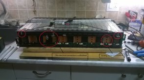
Hi GXMnow,Taking off the buss bar covers is not very difficult. There are a lot of clips, but each one is easy to release. If you have a high power soldering iron, I was able to solder my balance wires to the tab where each buss bar is soldered to the PC board that goes to the balance connectors. I wanted to use the balance connectors for a few reasons, the main one being, there are already fuses on the PC board for each balance lead, but I was not able to source the connectors. Since I am connected right to the buss bars, I did use inline ATC fuse holders with 7.5 amp fuses incase a balance lead shorts, it will just pop a fuse. I drilled a hole and cut a slot for each balance wire in the buss bar covers so I could put them all back on with the wires poking out.
[I had to delete the rest of the original b/c of word limits. My reply follows.]
Thanks for taking the time to write up all these v. helpful details - one thing - I think I found the connector as I was searching last night. From what I can tell, the module's boards have this, which pairs to the part we need (I think?): Molex Part 347910080, Mini50 Unsealed Receptacle, Single Row, Non-Bridged, 8 Circuits, Polarization Option A, Black. Two details on this - first there are (3) different polarization options for this part, and I think we need Polarization option A, but I am going to order and test the part before I know - I will post to confirm either way. 2nd detail: If I am right about this part, then the above is just the casing - you have to also order the crimp tins (8 pieces/connector), Molex Part 5600230448 - N.B. this particular one is the 22AWG tin; there is a different tin for the 24AWG connector. Now I have to figure out what wire and what crimper to get - not to mention trying to determine the pin-out - I am stuck in the middle of trying to figure out the 3p 8s module, as I attempt to explain here.
Your configuration in 14s seems reasonable to me. A few have also suggested this to me in the thread I linked above, but encouraging to get confirmation from you that it works well in the field. Separating the cells in the 3p 8s module using a dremmel sounds like a good, clean option - liquid electrical tape, gap over 3/16ths inch, some small holes in the bus bar cover, minimal additional resistance through your brackets, balancing leads soldering to the bus-bar/PCB connection - thanks for all these (and more) details - v., v. helpful! One q. here: you mention that the max. charge in this part of your module is 16.8V, so 4.2V/cell group. Is that just the nominal limit to illustrate the low risk of arcing, or are you actually charging to this maximum? If not, what max. (and min.) have you set? I ask because I think I would like to charge cell groups maybe to 4.0V or 4.1V, and probably limit the low to somewhere around 3.0V or 3.1V for longevity of battery. Do you have any thoughts on this? I'm a bit concerned by the Chevy recall that 'solves' the battery fire problem by limiting charge to 90%, depending on the year of manufacture . . . ?
[EDIT: I just saw that you answered my q. about voltages in an earlier post in this thread: "They have been charging to 4.1 volts per cell, and then discharging to 3.6 volts per cell for several month now with no issues at all."]
As for inverter/chargers, I am planning a dc-coupled system (don't even know if I'm going to use the grid-tie option, although I want to have it there in the inverter for a later design update) I had completely overlooked the Radian's "spring loaded wire terminals for a 30 amp 120/240 connection." Thanks for the tip - I'll take a closer look now. Glad to hear the Schneider XW is working for you, minus the software problems. I'll be comparing the Radian and Schneider more carefully after your comments, so will keep in mind the advice you got from them as I plan (yes, it is inadequate and they should allow full functionality with non-Schneider charge controllers. The daily work-around you're using sounds inconvenient for you to say the least. As you say, the solution shouldn't be hard for their software people. I'd want to see at least some willingness to provide a solution esp. when straightforward and low-cost to them.) As for the skybox, I was initially attracted, but for my own DC-coupled purposes, I believe the XW would be better - also one of their tech people told me that the transformerless design makes it problematic for surges like any electric motor start. I've got a bunch of surging loads - sump pump, refrigerator, pellet stove, etc., but I'm sure it is a good option for other applications.
I'll use your description as a ref. going forward, so will likely have more questions for you in future. Thanks again for taking the time to provide all this v. helpful info.!
Last edited:


![WP_20210318_13_33_36_Pro[1].jpg](/data/attachments/41/41516-a13e5b5912bcc9eba8af89196101018e.jpg)


") ) if that is optimal, but the cautions against this in the Orion document have me rethinking my configuration. Any of your input appreciated.
) if that is optimal, but the cautions against this in the Orion document have me rethinking my configuration. Any of your input appreciated.![WP_20210321_17_09_50_Pro[1].jpg](/data/attachments/41/41985-18cc48a85f7719c65386640a8016525b.jpg)