diy solar

diy solar

Li-poly SOC Discharge Curve to 0 Volts

Will Prowse

Forum Owner
Staff member
Moderator
Joined
Sep 19, 2019
Messages
3,399
Location
36° N 115° W
Complete discharge to decommission a large 3S Li-poly pack. SOC unknown. Pretty interesting:

lipoly test.jpg
scsdcd.jpg

The discharge curve seems to end at .5V, then flatten. Irreversible damage is obviously occurring at this point. It seems to recover to a baseline potential, around .5V multiple times before it dies.

Li-poly discharge curve has a very pronounced and well known drop off at low SOC, but I have never plotted out the voltage to 0V.

Not very useful information, but super cool! Any battery chemists wish to share what is occurring here?
 
Last edited:
Nickel Magenese Cobalt Oxide pack being discharged to zero. Very interesting to see this one hold at .5V, similar to the Lipoly pack above.

1111.jpg
scdscd.jpg
 
Will be interesting to set my new electronic load at constant voltage discharge to 0v and plot the current it takes to keep it pulled that low as compared to the voltage.

It looks like your load keeps turning off and on and that is what is causing those weird spikes. It's really hard to hold 0v and I think this HP load may handle it a bit better. Do you know the minimum voltage limitations of your load?

I have some used CALB CA100 cells that I've been doing all sorts of abusive testing with.

Come to think of it the data acquisition unit can plot current and voltage simultaneously, so it will be a great comparison to the data you collected.
 
May I ask what kind of elecronics load do you have, mlae and model, that can maintain constant Voltage as the battery is discharging so the battery Voltage will keep going down as it is discharging? May be you mean constant current load?
 
May I ask what kind of elecronics load do you have, mlae and model, that can maintain constant Voltage as the battery is discharging so the battery Voltage will keep going down as it is discharging? May be you mean constant current load?
My load is an HP 6050A mainframe loaded with 6 HP 60502B 60 volt 60 amp loads.

It can do CV, CC, CR and CW
 
So I was thinking about this quite a bit - @Will Prowse does your battery tester that is plotting the graph goes all the way to 0 ohms resistance, effectively a short? Part of me thinks there is some level of voltage required to push power through the fets/power devices, and at .5 volts it can't overcome the resistance of the tester. Do you think there is some plausibility to this logic?

I'm thinking of seeing how my load responds to this situation, my thought is I might have to put a power supply in series with the battery to bring the voltage that the load sees up a few volts, since current flows in a loop, it would effectively be able to drive the cells to a true "zero" point, and we could create some scientific plots doing so.

I am going to add this to our video idea board, essentially what happens when LFP batteries are over discharged. If a cell hits 0v is it instantly nuked? How long does it take for damage at 0v to occur? Does recharging a cell that hit 0v present a health/safety risk to the end user? I think this is a HUGE topic that is mostly overlooked in our community. I've got an HP 1000 watt 60v 100a power supply that I can set to a very stable, regulated 5 volts, and then put voltage sense leads on the electronic load, set at 0v (that is 0v at the sense leads, not at the load) which means we are effectively ignoring the effects of the load only being able to go _so low_

Am I crazy?
 
Will be interesting to set my new electronic load at constant voltage discharge to 0v and plot the current it takes to keep it pulled that low as compared to the voltage.

It looks like your load keeps turning off and on and that is what is causing those weird spikes. It's really hard to hold 0v and I think this HP load may handle it a bit better. Do you know the minimum voltage limitations of your load?

I have some used CALB CA100 cells that I've been doing all sorts of abusive testing with.

Come to think of it the data acquisition unit can plot current and voltage simultaneously, so it will be a great comparison to the data you collected.
Oh right, that is my fault because I was pushing 30A and then the voltage would drop to 0 for a millisecond, then it would turn it off, and the voltage would recover.

Yeah I am not testing this again because it is totally pointless. I am not dropping a 3S pack to .5V ever, so I don't see the point. I am only discharging to decommission a battery. Using the HP load might be better, but what point would it serve?

This is just a quick data plot for fun. I plan to never do this again because the data does not help anyone. That is why I posted it in this section.
 
My load is an HP 6050A mainframe loaded with 6 HP 60502B 60 volt 60 amp loads.

It can do CV, CC, CR and CW
Mine does constant current because that is all that matters for testing Amp hours. Are you actually going to use CV for battery testing? Why? Constant wattage might be fun.

When testing batteries to test for consistency with their data sheet (if that is your intended use case), CC is all that is needed. This is because many figures for batteries are rated in C rate, and that is relative to Ah capacity. Then you can use the tested average voltage during the cycle to figure Wh. Then compare to the data sheet or advertised capacity.

What is the point of the other tests? What are you testing for exactly?
 
So I was thinking about this quite a bit - @Will Prowse does your battery tester that is plotting the graph goes all the way to 0 ohms resistance, effectively a short? Part of me thinks there is some level of voltage required to push power through the fets/power devices, and at .5 volts it can't overcome the resistance of the tester. Do you think there is some plausibility to this logic?

I'm thinking of seeing how my load responds to this situation, my thought is I might have to put a power supply in series with the battery to bring the voltage that the load sees up a few volts, since current flows in a loop, it would effectively be able to drive the cells to a true "zero" point, and we could create some scientific plots doing so.

I am going to add this to our video idea board, essentially what happens when LFP batteries are over discharged. If a cell hits 0v is it instantly nuked? How long does it take for damage at 0v to occur? Does recharging a cell that hit 0v present a health/safety risk to the end user? I think this is a HUGE topic that is mostly overlooked in our community. I've got an HP 1000 watt 60v 100a power supply that I can set to a very stable, regulated 5 volts, and then put voltage sense leads on the electronic load, set at 0v (that is 0v at the sense leads, not at the load) which means we are effectively ignoring the effects of the load only being able to go _so low_

Am I crazy?
FireShot Capture 1044 - West Mountain Radio - CBA IV - Computerized Battery Analyzer_ - www.we...png
This is the states of my test equipment. 10mA, which is plenty for a solar battery tester. Solar batteries are huge, so this is entirely unnecessary. If I were testing micro batteries in a lab, then I would need more accuracy.

There are already studies that cover over discharged LiFePO4. Why would you think it is overlooked topic? You can do a capacity test after you discharge it to 0 and see the capacity loss. Or you will short a cell because a dendrite will punch through the separator. What would the point of our tests be? I do not understand the point. But if you want to do it, sure. But I think there is enough literature surrounding the topic to tell us not to over discharge our cells. It is a pretty straightforward process.
 
I think it is cool that you got that test equipment, but solar batteries can be accurately and effectively measured with a $100 shunt. Down to .01% in most instances. I like plotting the data for fun, but it really doesn't improve my results or help my viewers.

Edit: actually I just realized my battery analyzer has a ton of other features! I stuck to using only the discharge testing, but check it out:
FireShot Capture 017 -  - www.westmountainradio.com.png

And I just tried the constant power and it works great:
csdcd.jpg
 
Last edited:
Oh, I have a fun idea. Use your tester to cycle LTO at 10C discharge/5C charge for a few hundred cycles. And the efficiency/resistance graphed out. That would be super cool! @HighTechLab
 
Are you actually going to use CV for battery testing?
CV would only come in for essentially "clamping" the battery down to 0v,
test for consistency with their data sheet
I'm mostly testing for learning more about the quirks of different battery types, for example I found the curves for CALB plastic case LFP batteries to be more consistent decline, whereas some new aluminum case cells I was testing have some strange inflections around 30% SOC...We don't know why that happens, just something strange in the chemistry.

I have a hunch that the new aluminum case cells may have different over-discharge behavior than the old plastic case cells, we're finding there are tons of little details that vary.
I think it is cool that you got that test equipment, but solar batteries can be accurately and effectively measured with a $100 shunt.
Absolutely true, but it's like using a harbor freight volt meter or your klein or fluke. If your tester works for your uses, and you know your time isn't being spent screwing with equipment but rather doing the actual testing, we can both be more productive, and that's a good thing!
There are already studies that cover over discharged LiFePO4. Why would you think it is overlooked topic?
I just feel that everyone says "don't over discharge" or "don't go under 2.5 volts", but why? Most know in lead acid, overdischarging causes sulfation, but with LFP is that knowledge as common? Maybe, but I don't see people bring it up very often. If there is a safety risk such as dendrite formation, then that is really important for one to know!
 
CV would only come in for essentially "clamping" the battery down to 0v,

I'm mostly testing for learning more about the quirks of different battery types, for example I found the curves for CALB plastic case LFP batteries to be more consistent decline, whereas some new aluminum case cells I was testing have some strange inflections around 30% SOC...We don't know why that happens, just something strange in the chemistry.

I have a hunch that the new aluminum case cells may have different over-discharge behavior than the old plastic case cells, we're finding there are tons of little details that vary.

Absolutely true, but it's like using a harbor freight volt meter or your klein or fluke. If your tester works for your uses, and you know your time isn't being spent screwing with equipment but rather doing the actual testing, we can both be more productive, and that's a good thing!

I just feel that everyone says "don't over discharge" or "don't go under 2.5 volts", but why? Most know in lead acid, overdischarging causes sulfation, but with LFP is that knowledge as common? Maybe, but I don't see people bring it up very often. If there is a safety risk such as dendrite formation, then that is really important for one to know!
Yeah, good points.

And over discharge isn't a issue these days anymore because we use bms. When I first started out, we didn't have many bms options, so we ran lifepo4 with a bottom balance and set absorption manually. If a cell died, swap it out. Nowadays it's not a issue because we have LVD on our bms.

And sure, there is lots of studies on this:


The first study is great, scientific enough for my liking!

Where do you typically find studies like this? If you are using google, what search terms do you use?

Some times I end up doing tests because it's easier to do a test than find a good study like this, so maybe I'm missing something.
 
@HighTechLab @Will Prowse - A different application going down to zero may help explain things.

Draining a LifePo4 down to zero is not an uncommon occurrence with motorcycle starter-type LFP's. These are typically high-rate cells. Brands like Shorai, Anti-Gravity, Earth-X, you name it. Some come with BMS, some don't. In fact my first ridiculously expensive LFP bank was made from these - and I'm not a motorcycle rider!

But the fact is that some may forget to turn off parking lights, leave their glove-heaters on and wake up the next morning to find their $350 4ah lifepo4 dead at zero volts. Revival is mandatory when you are 600 miles from home. :)

Long story middlin' short:
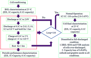
1) To recharge, you must get to it in time. We know that leaving cells at zero volts start to degrade chemically, but apparently not overnight. Or maybe in a few days. I don't have an exact timeframe, but the sooner the better.

2) To recharge from zero volts means you must use very very little current to get out of the steep discharge knee. Why? Aside from the whole dendrite thing, there is so much voltage potential at the charger, that running normal current can have the ability to blow out active material into the electrolyte, contaminating it.

In addition, what can also happen with too much current, is for lack of a better name, an "ion storm". What this means is that the lithium-ions can't intercalate fast enough and have no where to go. When they can't intercalate, they produce heat and possible secondary reactions. Which is bad.

One commercial charger manufacturer for lithium bike batteries knows this. When going into it's "save" mode, it applies very little current and won't start to charge with it's normal rated current until out of the discharge knee, and the cells have reached nominal 3.2v/cell.

MY TEST:
So other than it making sense, I wanted to SEE this so-called "ion storm" in process. How do I go about that without using my expensive cells as a test bed?

Answer: programmable hobby charger, and um, high-quality solar walkway light LFP batteries! Use high-quality of course. :) Seriously, I did the best I could. I went with Westinghouse cells. 500mah capacity LFP AA's.

Used the hobby analyzer to drain them to zero volts. A few times when they recovered a bit.

HAMMER TIME! Being safe about it with goggles, outdoors etc, I hit them up at 1C when they were at zero volts.

What I witnessed was an immediate rise in voltage (to be expected), but then a major stall! They barely got off the ground, and for all intents and purposes, no charging whatsoever was taking place. But they were being hammered at 1C nonetheless. Wouldn't rise. What I *think* I'm seeing here was the so-called "ion storm", where basically the ions were just in the mosh-pit. :)

Allowing them to rest, and using very little current, as little as I could provide until they reached 3.2v allowed me to hammer them at 1C ! Not that walkway solar lights like this...

So maybe there is a larger test looming:
Drag a known capacity big lifepo4 down to zero volts. Do not let sit longer than overnight that way.
Charge at something like 0.01C until the nominal voltage is 3.2v/cell
Change charge amperage to your desired nornal rate, and test for normal capacity at your normal lvd.

This way, you may not see any capacity loss. Or maybe you will, but I don't know the percentage. I just know that one of my favorite bike-battery chargers seems to follow this procedure, which is not an uncommon occurrence for bikers using LFP starter batts. Or, for all I know, this is only applicable to high-rate cells.
 
Back
Top