diy solar

diy solar

LiFePo4 4s4p 12v bank balancing?

Yurtdweller

Solar Enthusiast
Joined
Nov 23, 2020
Messages
275
Location
USA
I have a LiFePo4 bank with 4s4p.

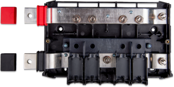
I have four 12v packs, each with it's own BMS. The packs are keeping good balance, individually. Each pack is wired to a Victron Lynx PowerIn busbar, with each pack having it's own megafuse.
The problem is that the packs are drifting out of balance from each other. This is because I have programmed my charge controller to stop charging at a voltage lower than the individual BMSs cut off charging. I did this just so that the mofs don't have to do the work of turning off charging.
Of course, this means that if one pack's wiring has more resistance, for whatever reason(chasing this issue), it will never get as much juice, thus will constantly fall farther behind.
Now, I'm going to balance them up by changing my cc settings so that the BMSs handle the top off(if the sun ever comes back), but I'm wondering what sort of active balancer, or whatever, I can install to keep the four seperate packs in balance?

Or should I just let the individual BMSs handle the charging control? I've heard that one should minimize how often the mofs have to activate.

I also wonder if I could simply install another 4 cell BMS to balance the four packs?
It seems the most logical, but that almost seems too easy? I'm guessing that the amp rating of the balance circuit would be too small for the job.

Or a 16 cell balancer?

I'm going to switch everything to 48 volts eventually, but my 12v 2kw inverter is all I need right now, and I don't want to swap everything over until/unless it dies, because I also have a lot of 12v appliances.
 
Now, I'm going to balance them up by changing my cc settings so that the BMSs handle the top off(if the sun ever comes back), but I'm wondering what sort of active balancer, or whatever, I can install to keep the four seperate packs in balance?

Or should I just let the individual BMSs handle the charging control? I've heard that one should minimize how often the mofs have to activate.

Correct. BMS should never be relied upon for routine charge/discharge terminations.

I also wonder if I could simply install another 4 cell BMS to balance the four packs?
It seems the most logical, but that almost seems too easy? I'm guessing that the amp rating of the balance circuit would be too small for the job.

Nope. You'd be paralleling cells via balance wires, and you coudl get some very wonky results/behaviors.

Or a 16 cell balancer?

Nope. That's kinda expensive and not as effective as one would like.

I'm going to switch everything to 48 volts eventually, but my 12v 2kw inverter is all I need right now, and I don't want to swap everything over until/unless it dies, because I also have a lot of 12v appliances.

The 4 batteries are going to be essentially the same voltage at all times, so they can individually balance themselves.

What is your absorption voltage that does NOT result in a BMS cut-off?
 
Correct. BMS should never be relied upon for routine charge/discharge terminations.


Nope. You'd be paralleling cells via balance wires, and you coudl get some very wonky results/behaviors.


Nope. That's kinda expensive and not as effective as one would like.


The 4 batteries are going to be essentially the same voltage at all times, so they can individually balance themselves.

What is your absorption voltage that does NOT result in a BMS cut-off?
I think I had the CC set to 13.5 cutoff, whereas the BMSs are set to 14.5.

I forgot about the BMSs being for series?rather than parallel ?

It had been my assumption that the four individual packs would just spontaneously self-level. That does not appear to be the case. At night, with only around a hundred watt draw, each pack is outputting equal wattage. I had half expected to see the higher packs outputting into the lower packs, but that is not the case. Jbd BMSs. I am also thinking, just this once, of hooking up my bench top ps, and manually raising the lower pack. Three packs are essentially level, but they are 62%, 62%, 65%, and 42%.

In fact, the lowest pack is outputting 2 watts more than the higher packs, right now, and I'm drawing less than 80 watts overall.

IMHO, if individual batteries within a parallel bank are within 10% of each other in terms of charge or discharge current, that's a big win. If all batteries are within spec, but with a larger deviation, that's still a win.

Want to make sure we're dealing with the correct terms...

If you're trying to load balance, that has nothing to do with the BMS. That's wiring and configuration. If you have a parallel connected bank with "diagonal" main leads, your middle two batteries will typically charge/discharge a little less than the outer two (the ones connected to the main leads)

Cell "balance" is the four cells being at the same SoC (not necessarily voltage) within each individual battery. The main terminals of each battery connected in parallel will ensure each battery is at nearly identical voltage, so there is no need to "balance" in that regard.

13.5V is pretty low for an absorption voltage (but a great float voltage). IMHO a minimum operational absorption voltage is 13.8V.

Since there's a good chance your cells are out of balance, I would set absorption to 13.8V, float to 13.5V and allow for at least 4 hours of absorption.

Set each BMS to balance at 3400mV and 10mV difference with balancing active at all times (not just during charge).

Check them tomorrow an hour into absorption and record the individual cell voltages. If all are at about 3.45V, each battery is fairly well balanced.
 
When I set up series batteries I use individual 12V charge controllers. Depending on your existing PV arrangement that might still be the simplest method to prevent the problems caused by series batteries ending up with differing SOC.
 
I will go though my settings again. I will use:
  • Absorption: 13.8V
  • Float: 13.6V
I will set my BMSs to cut charging above 14.2. I don't have a shunt right now, and my CC and the BMSs rarely agree, so I will have to fudge some numbers.

I don't have a diagonal. The Victron bus bar (lynx PowerIn) see pics, has both terminals at the same end, but they are VERY large, so I figured this would present minimal resistance issues. I suppose I could reverse one set of cables?

I also just received my torque wrench in the mail, and will need to go through my whole bank and check everything. I will say that 70in/lbs is much higher than I originally tightened everything:/

When I received the cells, I sorted them by IR. I suppose this could be affecting their discharge rates. I'll see if I can find my notes. They were extremely similar, and I was not originally intending to build a bank, so the cells with the lowest IR are together, and the cells with the highest IR are together. I was going to resell half of them, but I couldn't bring myself to do it:p

The individual cells in each battery pack are staying balanced very well.

I will state that each 'battery' (collection of four cells) are not reporting equal SoC, but upon a closer look, they are all within .01v of each other, so I suppose the apparent differences in SoC may be a glitch of the BMSs, and the fact that I have not topped off in several days, due to bad weather.

Perhaps I am worried about nothing:/

Thanks for your help. It helped me notice a few things just talking through it. I'm a little OCD sometimes:p
.
 

Attachments

  • cat-122015Lynx power in (top_open).png
    cat-122015Lynx power in (top_open).png
    396.6 KB · Views: 4
Last edited:
LOL
When I set up series batteries I use individual 12V charge controllers. Depending on your existing PV arrangement that might still be the simplest method to prevent the problems caused by series batteries ending up with differing SOC.
Lol, no. I'm using a Victron 150/100, which cost more than my first car, and I'm in parallel, not series. My system has to move 5 times a year, too, and I want to keep it as compact as possible, so I'm not going to buy four more CCs, with all the attendant cabling, even though each one would only need to handle 300 watts. After rechecking my numbers, I realized that each battery pack, while not displaying the same SoC, are showing nearly equal voltage. I made a big deal over nothing, it seems:/ Thanks for the idea, though. I will keep it in mind. Such a thing never occurred to me, though it would provide tremendous redundancy.
 
I will go though my settings again. I will use:
  • Absorption: 13.8V
  • Float: 13.6V
I will set my BMSs to cut charging above 14.2. I don't have a shunt right now, and my CC and the BMSs rarely agree, so I will have to fudge some numbers.

I would not do this. Set cut-off to 3.65V/cell and 14.6V for pack.

I don't have a diagonal. The Victron bus bar (lynx PowerIn) see pics, has both terminals at the same end, but they are VERY large, so I figured this would present minimal resistance issues. I suppose I could reverse one set of cables?

Gotcha. If your battery cables to the Lynx are all the same length, then current balance should be good.

I also just received my torque wrench in the mail, and will need to go through my whole bank and check everything. I will say that 70in/lbs is much higher than I originally tightened everything:/

Just make sure you're not going to ft-lbs.. :p


When I received the cells, I sorted them by IR. I suppose this could be affecting their discharge rates. I'll see if I can find my notes. They were extremely similar, and I was not originally intending to build a bank, so the cells with the lowest IR are together, and the cells with the highest IR are together. I was going to resell half of them, but I couldn't bring myself to do it:p

The individual cells in each battery pack are staying balanced very well.

Below 3.4V/cell, even imbalanced cells will have highly similar voltage.

I will state that each 'battery' (collection of four cells) are not reporting equal SoC, but upon a closer look, they are all within .01v of each other, so I suppose the apparent differences in SoC may be a glitch of the BMSs, and the fact that I have not topped off in several days, due to bad weather.

Since you're likely not charging to the "full" voltage value in the BMS, it's not synching, and you're getting drift with the short cycling.

Perhaps I am worried about nothing:/

Probably mostly, but it's better to truly know.

Thanks for your help. It helped me notice a few things just talking through it. I'm a little OCD sometimes:p

(y)
 
Can you easily disconnect one bank at a time? So you could top up one bank at a time watching for HVD?
 
Can you easily disconnect one bank at a time? So you could top up one bank at a time watching for HVD?
Well, I finally had enough sun to top off all four packs, with the cc set to charge past the top voltages in the BMSs. Then I took notes on the average variance between the cc and the packs. I don't run a shunt at the moment, so my cc and my packs never show equal voltages. Then I reset the cc to stop before the BMSs are forced to shut things down. The BMSs show about .3v higher voltage than the cc when the batteries are at 100 and charging has ceased.

To answer the question, I could easily disconnect each pack, (I've considered adding switches)but allowing the BMSs to stop charging, just once, I don't think that that is a big deal. This has allowed all batteries to charge to the same level.

Also, as I stated above, it turns out that all the packs were at roughly the same voltages, it was me reading only the reported SOC on each BMS that caused me some concern.

I'm away from home for a week or two, so I won't be able to mess around further until later in the month.

I suppose I should get a smart shunt for my Victron Smart controller. My old shunt was the bmv-700, and I don't have a way to let it communicate with the controller, so I didn't
include it in the new build. I think that that communication would require a cerbo gx, and I don't plan to buy one of those.

Step into the blue light.... It's a safe place.

Get the Cerbo-S w/o a display and a couple of VE.Direct cables for the BMV and MPPT... will only cost "a little more" than a SmartShunt, and you won't have any leftovers... and you'll have magic in your life... a feeling of total blissful control and logs... lotsa logs.
 
batteries in parallel are all at the same voltage at the buss bars but can have different voltages due to the resistance of each path. The resistance with be the total of wire, connections and IR of the individual cells. This difference is straight up Ohm's law V=Ir. So, when you are bulk charging, the difference in resistance with create different voltages across the batteries in the pack. When you are trickly charging, I is very small so the voltage drop is also small.
Because of this, a longer absorption time is your best friend in letting the higher resistance pathways catch up because when the low resistance batteries get to the absorption voltage, they increase in resistance and the charge to those batteries slows down. The batteries that are lagging behind will then have lower resistance so they will continue to take charge until they to hit the absorption voltage.
If you are setting absorption by time it will need about 4x the time to allow all batteries to get full.
I have a 2p4s 560Ah single pack on my boat and set absorption to 13.6v for 30-minutes. My motorhome has two 460Ah packs in parallel and I absorb them at the same voltage of 13.6v but set the absorption time to 60-minutes. They have Bluetooth so at the end of absorption, I check the current going to the two batteries and if one is taking significantly more current, I increase the absorption time.
I reduce the time by 15-minutes after a while to see if the shorter time will maintain a close match so that the time is as short as the batteries will allow.
If you are charging with a straight CC profile (bulk, off) with no absorption, then you are guaranteed to get drift because the resistance is each string will never be exactly the same.
 
Back
Top