RobertGreen
Solar Enthusiast
- Joined
- Mar 15, 2021
- Messages
- 308
Running conductors in parallel is explicitly allowed in the NEC at least for large conductors in certain applications where a massive enough single conductor would be impractical. See section 310.Here's info about certification: https://ramuk.intertekconnect.com/W...e5daea9b30cb7d3c862587ec0012f22c?OpenDocument
I am permitting this project and trying to do everything to code. I am trying to set this up in a legit way and not cut any corners or do things in a non-standard way. To me, bundling 3 wires seems non-standard.
You just don't run into it very often in residential settings.

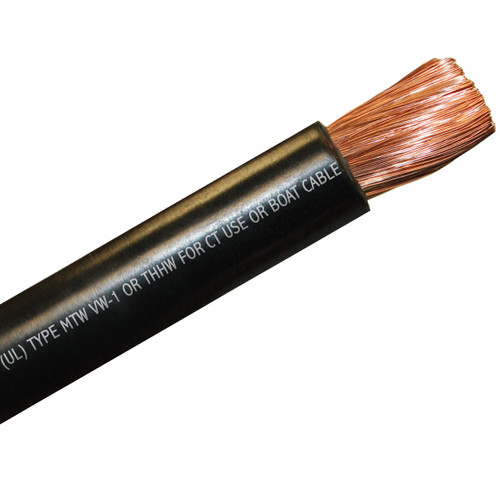
") That said, I was finally able to find a wire at 4/0 that actually says the AMP rating (405A when dry). I may not buy this specific wire but I think this will cover me:
That said, I was finally able to find a wire at 4/0 that actually says the AMP rating (405A when dry). I may not buy this specific wire but I think this will cover me: