• Have you tried out dark mode?! Scroll to the bottom of any page to find a sun or moon icon to turn dark mode on or off!

diy solar

diy solar

LiFePO4 prismatic cell short circuit current and main circuit protection

A stalled universal motor sees DC not AC in its windings, inductance would hold off the AC component of a step function when switch closed, but then current rises until limited by wire resistance.

A universal motor spins up until back EMF counters applied voltage.
Higher voltage, spins faster. Lower voltage, spins slower.

Ancient slot car or other toy motors were brush type, could be permanent magnet or wound field (universal.)

Your drones may have all been BLDC, 3-phase motors with inverter drive. So could change what you observe. Current limited to what FETs could handle by control electronics.


AC induction motors provide more torque with slight RPM slip below line (or VFD) frequency.
Split-phase induction motors have poor starting torque, depend on capacitor to give a bit of phase shift. (some technique to make them start without capacitors too.)
3-Phase motors get three 120 degree phases and have full torque from a standstill. Or higher, with full voltage and excessive current. VFD ramp them up with PWM limiting current while varying frequency.


Permanent magnet motors driven by VFD I think are locked to speed of driving frequency. Torque is angle between rotor and rotating magnetic field. VFD varies PWM as needed to limit current and achieve torque.
 
That's very strange I'm going to have to research that. Typically when you have a voltage drop of any kind even with inductive load, the current goes up. That's why you can't run motors with lower voltage because they heat up excessively. Until the laquer on the coils starts to smoke. Then it creates a massive short circuit. I'm going to have to put a meter or scope on a DC motor when starting with lithium iron phosphate. They startup so much faster with that higher voltage. No struggles.
Simplified explanation would be somewhat following:

Permanent magnet and shunt wound DC motors: voltage sets the motor speed and current is directly proportional to applied load(torque)
Series wound DC motors are funny animals and they spin faster with smaller load up to a point that they can explode if run without connected load. But also for these more voltage =higher rpm, more current = more torque

Synchronous AC and BLDC(subset of synchronous permanent magnet AC motor) spin at exact speed dictated by the frequency.
These draw whatever current (power) needed to stay at the speed (thus name synchronous) . Lower voltage means higher current to maintain same output shaft power. Induction motor spins at slightly slower speed("slip") than dictated by the frequency but also for these lower voltage means higher current to maintain same output shaft power.

Some of the latest cars could have combined starter-generator that is sort of BLDC but these are not common by any means. IIRC for example Ford has used these in some 48v MHEV's (mild hybrid ev). OT: These are going to be interesting option for 48v genset once these reach scrapyard prices. https://www.valeo.com/en/catalogue/pts/48v-belt-starter-generator-ibsg/
 
Don't forget about the AC motors that have fly-weights built into them. They have the capacitor in circuit to phase shift the voltage a bit until they are spinning and once the motor is up to speed the fly-weights remove the cap from the circuit or switch from the starter cap to the run cap.
 
Don't forget about the AC motors that have fly-weights built into them. They have the capacitor in circuit to phase shift the voltage a bit until they are spinning and once the motor is up to speed the fly-weights remove the cap from the circuit or switch from the starter cap to the run cap.
Single-phase heretic! 😆
Never seen one but I have heard stories of such motors used in far away countries that presumably have only single phase available in residential installations. :geek:
 
Yes exactly

I'm putting lots of batteries on my resistor bank and I cannot get above 560A with the packs that have an internal BMS. Would be cool to see someone post a higher results.

Something that occurred to might be a limiting factor with all LFP batteries... the bus bars between them... in the dumfume 300ah i mean 280Ah battery had really wide but paper thin aluminum bus bars between the cells. If there were a dead short with failed BMS I wonder how well those would hold up in the confined space without causing problems. What happens to aluminum when it gets hot? Does it increase resistance?
 
Something that occurred to might be a limiting factor with all LFP batteries... the bus bars between them... in the dumfume 300ah i mean 280Ah battery had really wide but paper thin aluminum bus bars between the cells. If there were a dead short with failed BMS I wonder how well those would hold up in the confined space without causing problems. What happens to aluminum when it gets hot? Does it increase resistance?
Aluminium like Most conductors have positive temperature coefficient, ie resistance increases with temperature.
In extreme cases it is possible that thin bus bars would melt or ”explode” in direct short circuit if there is no fusing. Failed BMS possibly has enough residual resistance that it will limit the current to tolerable level even if it turns up in flames.
 
Back to topic, something to muster:

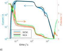
short-circuit currents seem to range 30C to 40C in these. Battery construction unknown, could be cylindrical high current or thick electrode high capacity prismatic cells.
Is the short circuit current higher in AGM or LFP battery? (Assuming under identical given conditions where all parameters are held constant, all else being equal, same rated batteries, except for that inherent chemistry)
 
Is the short circuit current higher in AGM or LFP battery? (Assuming under identical given conditions where all parameters are held constant, all else being equal, same rated batteries, except for that inherent chemistry)
Its like comparing apples and oranges… per Ah the short circuit current is in same ballpark for AGM and thick electrode lifepo4.
But High current optimized lifepo4 has lot higher short circuit current per capacity than our typical 300Ah cells. https://www.evlithium.com/A123-Battery/632.html
 
Its like comparing apples and oranges… per Ah the short circuit current is in same ballpark for AGM and thick electrode lifepo4.
But High current optimized lifepo4 has lot higher short circuit current per capacity than our typical 300Ah cells. https://www.evlithium.com/A123-Battery/632.html
Thanks. But I meant, if both the AGM and LFP are optimized for high power and load capabilities, then under identical given conditions where all parameters are held constant and all else being equal then where the short circuit current would be higher??
 
Thanks. But I meant, if both the AGM and LFP are optimized for high power and load capabilities, then under identical given conditions where all parameters are held constant and all else being equal then where the short circuit current would be higher??
What parameters you want to held constant? Capacity, weight, volume, price?
Each of them important for different application.
Capacity vise:LFP with maybe 2x short circuit current
Weight-vise: LFP 10x
Volume: LFP 5x
Price: AGM 2X
 
What parameters you want to held constant? Capacity, weight, volume, price?
Each of them important for different application.
Capacity vise:LFP with maybe 2x short circuit current
Weight-vise: LFP 10x
Volume: LFP 5x
Price: AGM 2X
So LFP delivers more short circuit current? Is it most of the time? Or not always?
 

diy solar

diy solar
Back
Top