Hi folks,
I've got a thorny issue that I hoping better understand with your help.
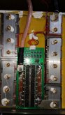
I have built a hybrid energy storage system (hess) using the follow components.
4 - Shunbin 12v 400ah lifepo4 batteries.
4 - Quantum Magnetics 16v 2000 farad super capacitors
I have wire the batteries and super caps together in parrallel creating four sets of lfp-supercap pairs. I then wired these paired sets together in series.
This configuration performed normally being charged with a 110 charger and a solar charger. The load on the battery bank was fairly light. - Refer compressor, lights, water pump, fans - and everything function perfectly.
I then completed the installation of a 20kw PMAC motor to replace the diesel engine and which the batteries were designed for. When I took the vessel out for sea trials I ran it up to 4.5 knots which was a load of 286 amps. The result was the BMS in the first lfp on the positive end of the series failed allowing only 3-5 volts. This failed BMS then prevented any energy out of the system except for the supwercap that was attached to that lfp. The electric motor then simply drained that one supercap and stopped.
So.
The BMS IMHO should have been able to handle 286 amps but it apparently didn't.
Did the supecaps overpower the BMS since they have less internal resistence?
Would it make sense to remove all of the BMS and replace with one BMS for the entire series?
Any insight of any kind greatly appreciated!
I've got a thorny issue that I hoping better understand with your help.
I have built a hybrid energy storage system (hess) using the follow components.
4 - Shunbin 12v 400ah lifepo4 batteries.
4 - Quantum Magnetics 16v 2000 farad super capacitors
I have wire the batteries and super caps together in parrallel creating four sets of lfp-supercap pairs. I then wired these paired sets together in series.
This configuration performed normally being charged with a 110 charger and a solar charger. The load on the battery bank was fairly light. - Refer compressor, lights, water pump, fans - and everything function perfectly.
I then completed the installation of a 20kw PMAC motor to replace the diesel engine and which the batteries were designed for. When I took the vessel out for sea trials I ran it up to 4.5 knots which was a load of 286 amps. The result was the BMS in the first lfp on the positive end of the series failed allowing only 3-5 volts. This failed BMS then prevented any energy out of the system except for the supwercap that was attached to that lfp. The electric motor then simply drained that one supercap and stopped.
So.
The BMS IMHO should have been able to handle 286 amps but it apparently didn't.
Did the supecaps overpower the BMS since they have less internal resistence?
Would it make sense to remove all of the BMS and replace with one BMS for the entire series?
Any insight of any kind greatly appreciated!