diy solar

diy solar

Lifepo4 Top balance problem and Voltage Problem

Joel007799

New Member
Joined
Jan 13, 2022
Messages
24
Hi everyone. My name is Joel and im actually from sweden. My post might not be ok becouse my lifepo4 cells are not for solarpanel. They are actually for a car sound system. So the problem:

I did get some lifepo4 cells last summer (2021). its 4 cells and they are 300ah cells. When i got them the Voltage was
1: 3,33
2: 3,33
3: 3,29
4: 3,39
So i decided to top balance them. I connected them in paralell and started to charge with 3A and set the voltage to stop att 3,65. So a few days later when they were done they all where att 3,63 and one at 3,64 now this cell that is att 3,64 is a big problem. When i then took them of carging and put them in series and put my bms on i started to charge them with regular 12V charger. Then when i reached 14,6 on the terminals i disconnected the charger and 3 cells where at 3,65 and one at 3,66. Now the problem, a few days later the cells are at:
1: 3,44
2: 3,44
3: 3,58
4: 3,39
Is 1 cell bad or what is going on? Im going to use this batterypack in my car as the car battery and to use this battery for my amplifyers. My alternator on the car is a 100A and maximum voltage on my alternator is about 14,3-14,4.

I hope someone has some answers becouse i dont know whats wrong.
// Joel from sweden :)
 
Is 1 cell bad or what is going on? I
Its never good when there are cell voltage differences like that but its not necessarily catastrophic. I would discharge the battery and recharge the battery a couple times to see how the cells behave together. It may be that you have to limit how high you charge your battery so that none of the cells runs away. I'd try charging to 13.8V to see if all the cells are reasonably close.

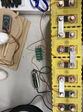
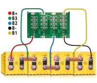
Your BMS looks like its wired in a strange way. All that I have seen have pin 1 go to the negative of cell 1 (on the negative end of the battery). Pin 2 to the positive of cell 1. Pin 3 to positive of cell 2. Pin 4 to the positive of cell 3. Pin 5 to the positive of cell 4 (the positive end of the battery).
Okey then i need to try to discharge them and then charge them again. I can limit the alternator to 13,9 V insted of 14.3 so that i dont risk the high cell go over 3,7. Here is a picture of the BMS where I bougt the cells:
c140b19cf1aa497b2be865df008e39a1.jpg
 
Here is a picture of the BMS where I bougt the cells:
But you've taken the liberty of moving (yellow for example) wires to the connected negative post of the subsequent cell instead of what is supposed to be the positive post of cell 1 (those 2 wires are used to measure the voltage of cell 1).
The black and yellow wire is supposed to show the voltage of cell 1: negative of cell 1 to positive of cell 1. Connecting yellow to cell 2 may yield a similar result but could be different based on the bus bar and an additional battery connection. And its hard to understand the way you have it.

The black and blue wire is supposed to show the voltage of cells 1 and 2 in series. Connecting blue to cell 3 is problematic.
But then cell 3 has no bms cabels at all, or maybe thats is how its supposed to be? Or should i put the green wire to the positive on cell 3?
 
But then cell 3 has no bms cabels at all, or maybe thats is how its supposed to be? Or should i put the green wire to the positive on cell 3?
Yes, green needs to go to positive on cell 3.
This is probably not the overall problem you are seeing unless there was a connection issue. Cleaning up connections and making it simpler might help somewhat.

I think you need to figure out how to make your cells work for you. And that will likely involve what you are attempting; charging to 13.9V and seeing if the cells stay within the parameters of the BMS (under 3.65Vpc in particular).
1: 3,44
2: 3,44
3: 3,58
4: 3,39
My experience is that all the weird chit happens on cells in positions 1 and 4. Label your cells and take notes of the voltage you have taken and how you got there. If you break apart your pack, it looks like cells 3 and 4 are your outliers. I would put the outliers as cell 2 and 3 position and your "more normal" cells in cell positions 1 and 4. This might help, i dunno.

Good luck. There is no magic, just a couple things you can do to make your battery more manageable and useful.
 
Last edited:
Yes, green needs to go to positive on cell 3.
This is probably not the overall problem you are seeing unless there was a connection issue. Cleaning up connections and making it simpler might help somewhat.

I think you need to figure out how to make your cells work for you. And that will likely involve what you are attempting; charging to 13.9V and seeing if the cells stay within the parameters of the BMS (under 3.65Vpc in particular).

My experience is that all the weird chit happens on cells in positions 1 and 4. Label your cells and take notes of the voltage you have taken and how you got there. If you break apart your pack, it looks like cells 3 and 4 are your outliers. I would put the outliers as cell 2 and 3 position and your "more normal" cells in cell positions 1 and 4. This might help, i dunno.

Good luck. There is no magic, just a couple things you can do to make your battery more manageable and useful.
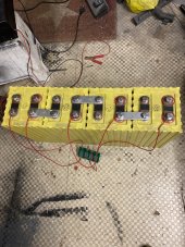
image.jpg
Now the cells that are 3,42 are in 1 and 4 position. Also the BMS is corret now? ?
 
Looks good on the cells. Hopefully it helps a little and you can get your cells/battery to behave at 13.9V.
Yeah i hope so too, i would have liked if i could have charged them as max as possible becouse more Volt is more power on amplifyers, i wonder if i call the company that i bought the cells from if i can replace that cell that is so high. then with some luck i can charge 14,3-14,4 at least but i will try it out first to se if it gets any more balanced when i have drove the car some and they have discharge some and then charged back up a few times. then maybe i can raise the Voltage if that works.
 
Okey, so maybe not worth replacing the high Voltage cell then?
Maybe not. If you can get them to behave at 13.9V (it does not sound like you have the option to go lower) then you should be good. Nobody has cells that behave exactly the same, its all about understanding your cells, doing what you can to get them to behave and live with them if you can.
 
Are you expecting to start your car with this battery? The starter may draw 100's of amps, likely more than what your BMS will handle.
Yeah im hoping to do that. I think it said on the website i bought them from Max 3000A discharge. But its a smal 4cyl engine so it is not that big. And i got big big copper cabels to supply and discharge the battery.
 
I think it said on the website i bought them from Max 3000A discharge.
Ok LiFePO4 batteries can offer up a LOT of power/amps. 3000A sounds wildly optimistic but i won't argue that point.

BUT your BMS is likely only rated for 100-200A. If you are able to pull 500A thru a 200A BMS, then that's a crappy BMS as its job is to cut out at some max amperage.

You may need to bypass your BMS for starting your engine if you need more amps than your BMS will allow. If you bypass the BMS, then you become the BMS and are responsible for monitoring cell voltages and other settings.

What BMS do you have?
I dont know what bms i have, its the One that came with the cells. But i dont think it does much for the cells. Im connecting the positive and negative directly to the battery so i dont know how this bms can cut of the battery. I belive its just a shit bms that is balancing the cells a little bit. I know that some bms you connect your cells thru the bms but that is not the case with my bms.
 
Back
Top