AgroVenturesPeru
New Member
- Joined
- Sep 19, 2020
- Messages
- 411
I feel this video deserves more discussion. Especially the part starting around the 50 minute mark. @Will Prowse recommended watching it in one of his recent videos.
I also feel this video deserves more explanation. I've always been told to use copper grounding rods, and even bought a kit with different conductor gels, sodium bentonite, concrete boxes, and 5/8", 8ft long copper rods with their wire clamps.
After watching this video, it sounds like I shouldn't have made the purchase.
If anyone else is knowledgeable on this topic, please elaborate. After watching the video, I'm left with the conclusion that "bonding" is the correct alternative to grounding.


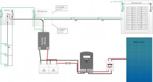
") Would the GFCI go first? I would think so. Anyhow, just curious if my setup is ok or not and was looking for feedback (even if it's something else that you see missing in the diagram)?
Would the GFCI go first? I would think so. Anyhow, just curious if my setup is ok or not and was looking for feedback (even if it's something else that you see missing in the diagram)?