diy solar

diy solar

Lishen cells: charge profile for 15 - 85 % SOC

hammick

New Member
Joined
Sep 19, 2020
Messages
283
My 280ah Lischen cells are in 16s configuration and I will be put into service soon on my 5,500 watt off grid inverter. My charging does not go through my Orion BMS so I need to be specific with my charge setting. I'd like to keep things between 15 -85 % SOC since I don't need anywhere close to 280ah. Please let me know if my plan based upon Will's recommendations sounds about right. Thanks for any advice.

Solar Charge Controller

Bulk: 56.4v
Absorb: 56.4v (absorb time set to 1 minute)
Float: 54.4v (so the sun powers the loads instead of the batteries)

Inverter charger (for generator charging)
Bulk 56.4v
Absorb: 56.4v (absorb time set to 1 minute)
Float disabled
LBCO 48v (that's as high as my inverter will allow)
HBCO: 58v (that's as low as my inverter will allow)

Temperature compensation set to 0 on both solar charger and inverter charger.

Once I get my Orion BMS talking to my equipment I will set up the LBCO, HBCO and temperature cutoff as failsafe settings.
 
If you don't need the capacity I would use 54.4 (3.4 per cell) as my CV voltage setting. I think that is what your Bulk voltage means.
 
I don't know that I would even attempt charging anywhere near high SoC w/o BMS protection without the ability to at least monitor all 16 voltages simultaneously.

There are no absolutes with LFP voltage. Charge current plays a key role in the voltage and SoC relationship. You can get LFP charged to 90%+ at 3.4V/cell with absurdly long absorption times... meaning even if you're FLOATING at 3.4V/cell, it's doing to keep charging until almost full.

However, a 1 min absorption at 3.4 Will leave you at a relatively low SoC.

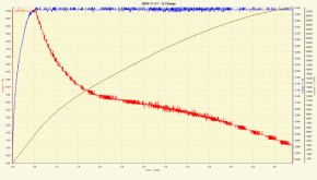
This is a 0.33C Charge to 3.4 from empty:

1609178283377.png

At 0.33C and 3.4V, it was only at about 18% SoC.

At 0.1C and 3.4V, it was about 87% SoC, but that took over 5.5 hours.

If you don't want charging to continue at float, your float needs to be 3.3V.

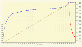
here's a charge to 3.65V @ 0.33C

1609178794969.png

Based on my data, if you pick 3.5V as a termination criteria, at 0.33C charge, you hit about 82%. In your case, that would be a 92.4A charge. If you charge at LESS than that current, you will exceed 82%.

Note that the above are SINGLE cell charges, so voltage drop is a factor. My setup permitted up to 0.04V drop at 0.33C. This means the actual cell voltage was 0.04V lower than the chart indicates. At charge termination with the lower current, voltage deviation was less than 0.01V. In this case, I would START at 3.46V as a termination criteria vs. 3.50 as your high voltage charging will have negligible voltage drop.

The best way for anyone to figure these points out is to use a quality battery monitor that tracks SoC. For your system, you can see how the relationship plays out for whatever your charge current and system resistances may be.

The same is true of the other end - discharge current also factors into the SoC/voltage relationship.
 
To summarize, you need a coulomb counter to know the state of charge for sure.

So with your hardware and available settings you would need to guess and check based on your actual usage to find values that get close to those targets. Probably different values depending on the session and weather etc.

Since your solar panels wattage and generator wattage are unknown to us it's impossible to even guess.
 
TBH, Not using the BMS when Charging is really playing Russian Roulette except with 3 rounds in chambers...
You WILL have cells that will wander, some will hit 3.65 and go over even. Absolutely 100% positive too.. You have been warned.
You can coulomb count and watchdog input but that will be no help at the cell level. If/when cells cross 4.0V and start puffing up it will be too late, Watch what your cells are doing when charging via the BMS, you will see the cells wander around and as you reach 3.400 they will really start to deviate.

Basic Inverter and Charge Controller Charge Settings

Below are the typical settings when using an inverter or charge controller with LiFePO4 batteries.
  • LiFePO4 batteries do not require Equalizing / De-Sulphation.
  • LiFePO4 batteries do not require Temperature Compensation for voltage.
CHARGE PARAMETER12V24V48V
Bulk Voltage14.0 - 14.628.0 - 29.256.0 - 58.4
Absorption Voltage14.0 - 14.628.0 - 29.256.0 - 58.4
Absorption Timedepends on charging profile being used
Float Voltage13.3 - 13.826.6 - 27.653.2 - 55.2
Low Voltage Cutoff11.0 - 12.022.0 - 24.044.0 - 48.0
High Voltage Cutoff14.629.258.4
Termination Current *≤0.05C≤0.05C≤0.05C
Termination Current Example: 100AH charge max 0.5C/50A, termination current = 0.05C/5A

* when using multiple batteries in a battery bank, reading current from the bank as a whole is ineffective.

LiFePO4 can be charged with either of these modes:

1-stage profile
(constant current (CC) aka Bulk Stage) profile will charge the battery ~95%. The 1-stage profile is sufficient, since LiFePO4 batteries do not need to be fully charged, they will settle to 95% after charging.

2-stage profile (constant current, constant voltage (CC-CV) profile aka Bulk and Absorption Stages). The 2-stage profile will charge the battery 100%. This may also have the effect of triggering a BMS HVD (High Voltage Disconnect), therefore take appropriate precautions by using conservative charge settings to begin with.
  • Optimal Charging will occur at 0.5C charge rate per battery. The number of batteries multiplies the amps required to meet 0.5C charge rate.
  • The ability for any single battery within a bank of batteries should be capable of handling the full charge & discharge potential of the system.
 
Thanks for the great info guys. I want to clarify that the BMS will be able to limit charging and discharge. It will do that through the Canbus settings and will control my Solar CC and Inverter Charger directly. I will set the LBCO and the HBCO more conservative than the BMS. The BMS settings will be a fail safe for LBCO and HBCO and obviously will be able to monitor individual cells and shut down the charger or inverter if a cell gets astray.

My Solar CC can do 60 amps but with my panels 40 amps is about the max in summer and in the mid 20s this time of year. My inverter charger can charge at 110 amps.
 
Hi have you compressed your batteries?
How many cycle will you get with your settings?
Yes batteries will be compressed using threaded rods like a lot of guys are doing. Not sure how many cycles I will get but since I don't need 280ah I will be limiting SOC to maximize cycles.
 
To summarize, you need a coulomb counter to know the state of charge for sure.

So with your hardware and available settings you would need to guess and check based on your actual usage to find values that get close to those targets. Probably different values depending on the session and weather etc.

Since your solar panels wattage and generator wattage are unknown to us it's impossible to even guess.
My BMS uses a hall effect sensor for Coulomb counting. I also have a Trimetric battery monitor and the Schneider Conext battery monitor. Both of those are shunt based monitors.
 
Back
Top