diy solar

diy solar

Lost on Battery/BMS wiring & config

myersfamilyhome

New Member
Joined
Feb 9, 2021
Messages
140
I thought I bought the right items but now I'm lost on how to wire properly. I have 32 New Eve 304ah LifePo4 Cells and 2 Daly 16s 300a 48v Smart BMS w/ Bluetooth. I was thinking that I need 2 16s BMS's for creating 2 banks of 16 for my 48v build. Now I'm lost on how to wire and setup. Any help would be greatly appreciated. I'm trying to get off my generator and on my solar but can't risk screwing this up.
 
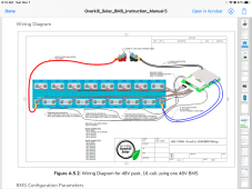
This is how Overkill BMS would be wired:

F1276D94-E962-4F98-A45A-2CFC478A5F40.png


You can download the overkill BMS manual. That will be good for reference. I have a smaller Daly BMS 30 amp BMS that only had a singl page wiring diagram for setup. Not sure if the 250 amp is better. Also recommend fusing that battery, not shown in the diagram.
 
This is how Overkill BMS would be wired:

View attachment 71589


You can download the overkill BMS manual. That will be good for reference. I have a smaller Daly BMS 30 amp BMS that only had a singl page wiring diagram for setup. Not sure if the 250 amp is better. Also recommend fusing that battery, not shown in the diagram.
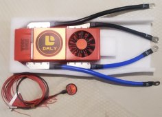
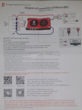
Thank you for the reference. Daly doesn't provide very good instructions. I've attached what was shipped along with a pic of one of the BMS's. The things that I don't understand are, why are there 2 P- and 2 B- wires (black and blue in the pic) on one BMS and how are they wired? If I have 2 banks of 16 do I set them both up with there own BMS and just parallel them together to a common bus?
 

Attachments

  • 20211107_074439.jpg
    20211107_074439.jpg
    316.8 KB · Views: 32
  • Screenshot_20211107-074219_PhotoScan.jpg
    Screenshot_20211107-074219_PhotoScan.jpg
    469.9 KB · Views: 35
And one little suggestion. When you install the balance leads, before you connect it to the BMS, use your voltmeter and check that each lead shows a 3.2v higher number than the one next to it, as in 3.2, 6.4, 9.6, 12.8, etc., adjusted for your actual voltage of course. A couple of times I've found that I made an error along the way and it will instantly fry your BMS if not caught before connection. With a 16S it's easy to swap a couple around.
 
The things that I don't understand are, why are there 2 P- and 2 B- wires (black and blue in the pic) on one BMS and how are they wired?
I don't have the Daly, but for my Overkill, I have two black leads and two blue leads. Each of those leads are 8 AWG, and instructions say to insert into a 6 AWG lug and crimp. Basically, if both the wires are 10 AWG, they go in an 8 AWG lug.

I'd like to hear from a Daly user.

I think overkill does that because two 8 AWG is easier to route, and maybe cheaper than, a single 6 AWG wire.

If I have 2 banks of 16 do I set them both up with there own BMS and just parallel them together to a common bus?
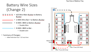
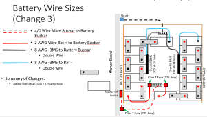
Yes. This is how I am doing it:

1636300977870.png
 
I don't have the Daly, but for my Overkill, I have two black leads and two blue leads. Each of those leads are 8 AWG, and instructions say to insert into a 6 AWG lug and crimp. Basically, if both the wires are 10 AWG, they go in an 8 AWG lug.

I'd like to hear from a Daly user.

I think overkill does that because two 8 AWG is easier to route, and maybe cheaper than, a single 6 AWG wire.


Yes. This is how I am doing it:

View attachment 71599
Awesome, so the double wires are to be used as if there was just a single bigger wire. Both B- will be connected together at the same location and both P- will be connected at the same location.
 
The things that I don't understand are, why are there 2 P- and 2 B- wires (black and blue in the pic) on one BMS and how are they wired?
The reason is that on the BMS the management of the current through the BMS is split between two sets of MOSFETs, just to reduce the current load on any one set of MOSFETs. So your battery negative does to both of the two B- leads, and then the loads and chargers go into the two P- leads.
 
The reason is that on the BMS the management of the current through the BMS is split between two sets of MOSFETs, just to reduce the current load on any one set of MOSFETs. So your battery negative does to both of the two B- leads, and then the loads and chargers go into the two P- leads.
Thank you so much for confirming. Now I need to understand where to put breakers to protect each bank, and how to size them appropriately. I know fuses can be used but would prefer breakers if at all possible.
 
Awesome, so the double wires are to be used as if there was just a single bigger wire. Both B- will be connected together at the same location and both P- will be connected at the same location.
Since this is not the same device, confirm from the manual, or wait for a Daly user.

There are some youtube videos out there with the Daly BMS with two leads. The ones I glanced at had each lead having its own lug.
 
Since this is not the same device, confirm from the manual, or wait for a Daly user.

There are some youtube videos out there with the Daly BMS with two leads. The ones I glanced at had each lead having its own lug.
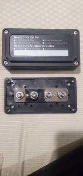
Not sure how that would apply on the battery connection but I can accommodate with this bus bar. Will connect the 2 P- of each BMS to a separate lug and then connect bus to SmartShunt.
16363029385027471363722801853108.jpg
 
Thank you for the reference. Daly doesn't provide very good instructions. I've attached what was shipped along with a pic of one of the BMS's. The things that I don't understand are, why are there 2 P- and 2 B- wires (black and blue in the pic) on one BMS and how are they wired? If I have 2 banks of 16 do I set them both up with there own BMS and just parallel them together to a common bus?
You have two leads because a single 2 gauge wire won't carry 300 amps. From what I can tell, 2 gauge is the largest Daly uses.
 
I think overkill does that because two 8 AWG is easier to route, and maybe cheaper than, a single 6 AWG wire.

JBD (Overkill) does it that way so they don't have to invest in a heavier copper trace on the PCB. They have scaled up lower amperage BMS to meet the desired amperage from customers.
 
Awesome, so the double wires are to be used as if there was just a single bigger wire. Both B- will be connected together at the same location and both P- will be connected at the same location.
That's correct. Notice that the two wires are different lengths, but would both connect to the same lug with ease. The connector Daly uses to attach the wires might be pretty much used only by Daly, so they use two rather than buying bigger connectors and wires for a limited market.
 
I don't have the Daly, but for my Overkill, I have two black leads and two blue leads. Each of those leads are 8 AWG, and instructions say to insert into a 6 AWG lug and crimp. Basically, if both the wires are 10 AWG, they go in an 8 AWG lug.

I'd like to hear from a Daly user.

I think overkill does that because two 8 AWG is easier to route, and maybe cheaper than, a single 6 AWG wire.


Yes. This is how I am doing it:

View attachment 71599
Do you have more info on your box build? Maybe some photos? I'm currently building the exact same config. Dual 8S with Overkill 100A BMS. I'd love to learn from your experience as I work through how to construct and wire.
 
Do you have more info on your box build? Maybe some photos? I'm currently building the exact same config. Dual 8S with Overkill 100A BMS. I'd love to learn from your experience as I work through how to construct and wire.

The build for the box I picture above is stalled. The RV is in the shop getting fixed, so I have not pulled the old battery out and put the new 2 X 8S one in.

Until I get it in front of me, I can't put the puzzle together. I do have all the parts, but don't really want to post links until I have the battery box in front of me.

The battery box is about 24" X 24", and it turns out with 1mm neoprene and .5 mm plastic shells to protect each cell may cause the 8S as pcitured to be too big to fit in the box, so I am may build it like this:

1638323120714.png

This is the box I already have in the RV that holds 4 golf cart batteries, which will be removed and the 8S placed in it.


I posted the link but can't make a recommendation for that tray for 280 ah EVE's until mine are physically in there. Installing the sliding battery tray was a huge pain because the plastic cardboard underbody was a huge pain to remove enough to put some shoring underneath so 250 LBS of batteries did not rip out the bolts. Not only that, but the black water tank was right under one of the holes I drilled so I was luck I didn't puncture it.
 
The build for the box I picture above is stalled. The RV is in the shop getting fixed, so I have not pulled the old battery out and put the new 2 X 8S one in.

Until I get it in front of me, I can't put the puzzle together. I do have all the parts, but don't really want to post links until I have the battery box in front of me.

The battery box is about 24" X 24", and it turns out with 1mm neoprene and .5 mm plastic shells to protect each cell may cause the 8S as pcitured to be too big to fit in the box, so I am may build it like this:

View attachment 74047

This is the box I already have in the RV that holds 4 golf cart batteries, which will be removed and the 8S placed in it.


I posted the link but can't make a recommendation for that tray for 280 ah EVE's until mine are physically in there. Installing the sliding battery tray was a huge pain because the plastic cardboard underbody was a huge pain to remove enough to put some shoring underneath so 250 LBS of batteries did not rip out the bolts. Not only that, but the black water tank was right under one of the holes I drilled so I was luck I didn't puncture it.
Thanks for the quick reply. Mine are 230ah, so maybe a little thinner, but still heavy. I'll just try to follow your progress. Thanks.
 
Thanks for the quick reply. Mine are 230ah, so maybe a little thinner, but still heavy. I'll just try to follow your progress. Thanks.
After doing the math and seeing the 280s may be too big, I wish'd I'd bought the 230s. Would have been 11.0 kwh instead of 13.4 kwh (if I did the math right), which is still plenty.

I'm only using that battery box because it was in there from the last build. There will come a point where the battery box is more trouble than its worth and out it goes. In the year and a half the lead acid batteries have been in there, I've opened it 0 times. All maintenance could be done with the battery box closed.
My batteries will be under a bed, so I plan to build the box, install it in the trailer, and then load in the cells. It's the only way I can manage the weight by myself. I'll build and test it completely outside the trailer first, to ensure fit with cells, cabling, etc., but then take it apart and rebuild it in the trailer. I also assume that once it's in, I won't need to access the cells unless something goes wrong with cell voltages, which I can monitor externally. Dealing with such large cells is a challenge in an RV for sure.
 
Access to the cells after the initial install could be helpful. I verified that all my connections were still tight. I did this a few times in the first year. Now I'll be doing it once a year.
 
I won't need to access the cells unless something goes wrong with cell voltages, which I can monitor externally. Dealing with such large cells is a challenge in an RV for sure.
You have a bit of confidence in your work!!:)
 
Back
Top