diy solar

diy solar

Low temperature PV string bypass relay/switching

Symbioquine

Solar Enthusiast
Joined
Jul 6, 2021
Messages
423
I'm curious whether anyone has worked out a circuit that bypasses one of the panels in a PV string at low temperatures?

It seems like such a device could be very simple and allow normal operation with larger strings than the temperature coefficient and absolute lowest expected temperature might otherwise dictate.
 
I have not heard of such a device, but it is an interesting idea. If you find anything, let us know.

My first thought when I read your post was you could use some relays to do it but That would require ongoing power in either on 'normal' or 'bypass' state. Perhaps a bank of low resistance FETs and a control circuit to turn them on/off.

One interesting idea is that it could be controlled by the voltage of the total string.... if the voltage gets close to SCC voltage limit, drop out a panel.

Along those same lines, it could just be set up to shut the whole string down. This would allow you to design for something more like the normal low temps but still be safe for the extreme low temps
 
I use a voltage sensor circuit, that places external loading across the array output when the volts get too high; this pulls the array voltage down from an otherwise excessive peak as could occur if the battery bank was on float with no load and freezing cold outside.
Only takes a small load of a couple of amps to limit the off load voltage peak.

Mike
 
My understanding is that the danger period is in the morning when the strings come up to voltage very quickly but there's little actual energy available, just a voltage which could possibly overwhelm the SCC input.

Sooooo. How about a FET based shunt regulator set to just below the SCC Voc limit.

Some ideas here https://www.edn.com/shunt-circuit-clips-large-transients-or-regulates-voltage/

@SolarForU2 your solution sounds like the above, do you have a circuit diagram??
 
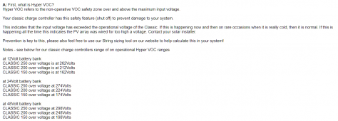
The Midnite Classic charge controllers have a feature called Hyper-VOC. Not sure how it's implemented, but the idea is that they protect against extended voltage increases due to cold. https://www.midnitesolar.com/faqPrint.php?faq_ID=233&faqCatName=Classic Charge Controller&faqCat_ID=57
1664003924269.png

If you used a relay to take a panel out of a string, you'd loose power till it was restored. Typically one can predict good string design / charge controller / battery voltage range for the local environment and greatly minimize this. A relay reducing power once in a while is probably not worth it and Hyper-VOC protection might do the trick.

If it was happening often, then better to re-arrange the strings to avoid significant loss of power - especially in the winter.

All together, this might be why it's not 'a thing' :).
 
Last edited:
I use a voltage sensor circuit, that places external loading across the array output when the volts get too high; this pulls the array voltage down from an otherwise excessive peak as could occur if the battery bank was on float with no load and freezing cold outside.
Only takes a small load of a couple of amps to limit the off load voltage peak.

Mike
I like this idea. Would you share more info on what you did? Circuit diagram? What load do you use? I don't like to reinvent the wheel if at all possible;)
 
I like this idea. Would you share more info on what you did? Circuit diagram? What load do you use? I don't like to reinvent the wheel if at all possible;)
If you read the post #5, all info already provided, including pcb and schematic.
 
You can shut the string off completely with a dc voltage monitoring relay that signals a pv disconnect contactor.. to make the contactor handle the potentially aggressive arcing, use a 3 pole and run the pv positive through all three poles to distribute the arc if it does happen to break under load. Seimens makes good DC high voltage monitoring relays.
 
I experimentally locked my voc to under 60 volts using Zener diodes. I couldn't find a 60 volt Zener so I used two 30 volt zeners in series. They were only rated 10 watts so I was concerned that I may blow them but the scc took most of the current. My Vmp was 54 so they didn’t take much abuse and kept the input voltage to the scc below 60.
 
I experimentally locked my voc to under 60 volts using Zener diodes. I couldn't find a 60 volt Zener so I used two 30 volt zeners in series. They were only rated 10 watts so I was concerned that I may blow them but the scc took most of the current. My Vmp was 54 so they didn’t take much abuse and kept the input voltage to the scc below 60.
I used Zeners for a load dump on a micro-hydro turbine, but I used 4 35W zeners in series to get the correct voltage and be able to dissipate the 120W the turbine would generate.

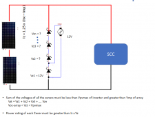
Whit solar panels, the zeners 'only' have to dissipate enough energy to bring the panel voltage down to the Zener trip voltage. Trying to calculate what that current needs to be is a bit of a challenge. I guess the starting point would be the difference between Isc and Imp..... Then add at *least* 25% for a safety margin. Since the difference between Isc and Imp tends to be relatively small, it may turn out that this is not that large of a current.


The calculated current multiplied the zener trip voltage will give you the wattage the diode needs to be rated for.
Pz = (Isc - Imp) x 1.25 x Vz

However, keep in mind that most power zeners are specified for having large heat sinks in order to operate at the specified wattage.

One more trick for using power zener diodes as a dump load: Make one of the Zeners a 12V zener and then put a 12V computer fan in parallel to it to help cool the diodes.

1665010545783.png

Warning, I have only used zener diodes for dump loads on micro-hydro. I have never used them on solar as shown above..... but I it seems like it should work.
 
Last edited:
Pz = (Isc - Imp) x 1.25 x Vz
This formula works good when the system has reached steady state operation.
The probelm I see is that some mppt controllers take some time to determine mpp. I have one that can take up to 4 seconds and for a portion of that time it sinks very little current and the zeners may have to take whatever current the panels produce at the zener strings trip voltage.
 
OK So lets say you want to clamp the voltage to 500VDC and on the coldest day of the year Voc is 520V. For my array (example), Isc = 9.82, Imp = 9.41. (9.82-9.41)x1.25x500V = 256 Watts.
You can get 100V 50W zeners stud mount. Mount 5 to an aluminum finned heat sink. I would think the zeners would only need to clamp the voltage for a few minutes at most. Tolerance of the zeners is +- 5%. So the zeners would have to be hand picked and then tested as a unit.
Intriguing idea due to it's simplicity.
 
This formula works good when the system has reached steady state operation.
The probelm I see is that some mppt controllers take some time to determine mpp. I have one that can take up to 4 seconds and for a portion of that time it sinks very little current and the zeners may have to take whatever current the panels produce at the zener strings trip voltage.
Edit: After thinking about this more, I have come to realize this may not be an issue. Please see post 16.

Hmmm good point. That could be a lot of power. The question is, would the zeners overheat and burn out in those 4 seconds? This would be a good reason to provide more than 25% margin on the current.

In the typical case the MPP would start tracking in the morning before this is an issue. It is the off-case where something else happens that could be an issue. The most severe case would be that the string disconnect is switched from off to on while the panels are in full sun on a cold day.
 
Last edited:
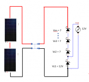
If you do this you would want to put the PV disconnect before the parallel zener diodes.

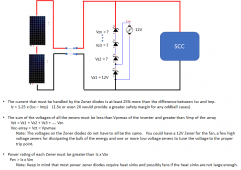
Edit: Updated picture and notes.

1665097762882.png
This formula works good when the system has reached steady state operation.
The probelm I see is that some mppt controllers take some time to determine mpp. I have one that can take up to 4 seconds and for a portion of that time it sinks very little current and the zeners may have to take whatever current the panels produce at the zener strings trip voltage.
As I was drawing the above and thinking about the problem it occurred to me that it may not be as bad as it sounds. It comes down to how long the zeners can be in parallel to the solar panels without the SCC:

1665085929739.png
As the zeners start conducting current, the panels will find an equilibrium where the current and voltage are balanced at someplace on the I-V curve of the panel. If the current got as high as the Isc-Imp, the voltage would be below the trigger point of the zeners. Consequently, even if the SCC is completely disconnected, the Zeners will not take more than Isc-Imp current. Having said that, I would consider the 25% multiplier on the current an absolute minimum safety margin. It would probably be better to have a higher margin.
 
Last edited:
You can get 100V 50W zeners stud mount. Mount 5 to an aluminum finned heat sink. I would think the zeners would only need to clamp the voltage for a few minutes at most.
The Zeners will have to clamp the voltage for as long as the batteries are full and the SCC is not taking current....or till the temperature of the panels rise and the Voc goes down.

I would not count on the temperature rising fast enough so the system needs to be designed for a sustained period of the zeners conducting. However, if the zeners are in the same cold temperature, the heat sinks will be much more effective. (This is an argument for putting the zeners at the panels, not at the SCC like my previous diagram)

BTW: The Zeners do not have to be all be the same voltage, You could have one at 12V to run a fan, several at a high voltage to take the bulk of the energy, and one final one to 'trim' the trigger voltage. The power rating for each one is determined by Vz x I, so the lower voltage zeners do not have to be as high wattage as the lower higher voltage ones.

Also, it may be better (lower cost?) to use more lower voltage, lower wattage zeners than to use fewer high voltage, high wattage zeners.
The cost, number, voltage, and wattage of the zeners can all be adjusted to optimize price and performance.
 
Last edited:
@McKravitts Thank you for posting about the Zener Diode as a possible solution. I had used Zeners for micro hydro but that needs to dump the full load so Zeners do not scale very well for turbine dump loads. I had never considered that with solar, you only have to dump a small fraction of the load so it may be a viable solution.

If anyone else tries this solution, please post about it. I am curious to hear about any real-world results and/or issues.
 
Hey guys, tagging along here as I am in need to do something similar (did not want to start a separate thread). I have available two sunpower x22 360W panels in which the specs are:
  • vmpp 59.1v
  • impp 6.09a
  • voc 69.5v
  • isc 6.48
My MPPT which I am locked into (ecoflow delta 2 + EB) is limited to 60V. I want to overpanel with these to get a nice wide charge during more hours of the day since they are available for cheap to me.

So, protection per panek would look like.... 1.25x (isc-imp) = .4875 x (zener trip voltage targeting 59v) = 28.272w
Or slightly safer at .585 X 59v = 34.515w

Does this look right? Really appreciate any feedback as I really want to use these panels but want to make sure I do not kill off my delta 2! I also love the idea of the fan to cool the setup and how you did it / just in case. This would require 1 protection circuit per panel so lower cost zeners can be used.

Looking at diodes... Found these 10w rated units. I could do 4qty of 12v and 2qty of 5.6v to target 59.2V (will have to test to make sure the tolerance does not exceed 60v). But the 6qty 10w total SMD devices will work out nicely I think. I can make a clean PCB using thick 2oz copper with good heat dissipation and for good measure, add a heatsink to the top of diode string with fan output on the PCB.

Am I calculating dissipation of each zener correct? .585x5.6 = 3.276w for the 5.6V zeners and 7.02w for the 12v zeners? @FilterGuy
 
Last edited:
@MRGarage It sounds like you'd be really pushing the concept I was asking about to its limits... I was looking for ways to make panel arrays that would work fine 99% of the time safer for the edge cases, but it seems like you're looking for ways to make panels that would blow up your charge controller 99% of the time work anyway.

Why are you considering risking a $1500 device to avoid spending ~$400 on lower Voc panels? I'd imagine you could either resell or use the SunPower panels on another project.

Obviously, hats off to you if you do get it working (and please share the details either way). I'm just asking the question since I'm a bit risk averse myself ?
 
Back
Top