diy solar

diy solar

LV6048 output neutral-ground bonding?

vrs

New Member
Joined
Jan 8, 2022
Messages
5
Just picked up an MppSolar LV6048 and noticed that they bond the output neutral to ground! Not clear why. If your split phase input is from a panel where ground and neutral are bonded, which is always the case if the panel is the first disconnect after the meter, you would like to preserve that original bond and not bond again downstream. When the 6048 is in grid pass-through mode, if it's wired to a subpanel with unbounded ground and neutral as it should be, you would like your main panel to be the only source of neutral-ground bonding, per Code.

For inverter mode, the neutral-ground bond at the output is ok. So if you're off-grid completely - with no grid connect for back up, you'd be good to go. But when using the grid for back up, the neutral-ground bond after the main panel NG bond is a safety concern. Also likely to make the ground a current carrying conductor, as opposed to a purely fault clearance conductor that's energized only when a hot conductor shorts out.

Quick Qs:

1. Anyone own a 6048 tied to the grid off a main breaker panel? If so, have you tried clamping the ground wire to scope out potential current on the line?

2. Anyone know if there's some kind of mode dependent switching inside the 6048 that opens and closes the neutral-ground bond?

Maybe I'm missing something obvious, and this is a non-issue. Maybe measuring a dead short with the unit off is misleading. I did read through a thread on one of the Growatts having this problem, but did not see any simple solutions.
 
MppSolar LV6048 and noticed that they bond the output neutral to ground!
Maybe measuring a dead short with the unit off is misleading.

The MPP support group tells me that the LV6548 uses an internal dynamic N-G bond relay. (The NG-Bond is only generated when NOT in pass-through mode). If the LV6048 does the same, it is possible (Likely?) that the relay is in the 'bonded' mode when the inverter is off.

One way to test this is to check for a current on the AC-in Ground wire when the unit is in pass-through mode and has a load. If there is a second bond inside the inverter, there will be current on the ground wire. (Up to half of the total current will be on the ground wire)

When you get this figured out, please let me know.
 
Just picked up an MppSolar LV6048 and noticed that they bond the output neutral to ground! Not clear why. If your split phase input is from a panel where ground and neutral are bonded, which is always the case if the panel is the first disconnect after the meter, you would like to preserve that original bond and not bond again downstream. When the 6048 is in grid pass-through mode, if it's wired to a subpanel with unbounded ground and neutral as it should be, you would like your main panel to be the only source of neutral-ground bonding, per Code.

For inverter mode, the neutral-ground bond at the output is ok. So if you're off-grid completely - with no grid connect for back up, you'd be good to go. But when using the grid for back up, the neutral-ground bond after the main panel NG bond is a safety concern. Also likely to make the ground a current carrying conductor, as opposed to a purely fault clearance conductor that's energized only when a hot conductor shorts out.

Quick Qs:

1. Anyone own a 6048 tied to the grid off a main breaker panel? If so, have you tried clamping the ground wire to scope out potential current on the line?

2. Anyone know if there's some kind of mode dependent switching inside the 6048 that opens and closes the neutral-ground bond?

Maybe I'm missing something obvious, and this is a non-issue. Maybe measuring a dead short with the unit off is misleading. I did read through a thread on one of the Growatts having this problem, but did not see any simple solutions.
First, you would need to power up the unit and recheck it. I think you will find the unit has pass thru ground under grid power without a N-G bond. Only when running under inverter power will you see a N-G bond, that is at the inverter which is source.

Second, I know Dan had some trouble with his LV6548 https://diysolarforum.com/threads/lv6548-grounding-issues.21531/ but the solution was to run the ground direct from the panel instead of thru a subpanel with a ground busbar.
 
Thanks much to all for the guidance, much appreciated.

I caught Dan's video on youtube today,


And I read his reply to Sanwizard where he writes: "I ended up changing my ground from the panel directly to the inverters (It was in my junction box on a terminal strip with the other circuit grounds)."

Maybe that's the secret sauce.

Interestingly, I spoke to a fellow named Ian at watts247, and he said that there should be no continuity between output ground and output neutral with the unit powered off. Yet there is. Let that be a weird head scratching data point that maybe has no meaning. If Dan's solution is real, direct ground wiring from panel to inverter, then issue closed. Might also imply there is some internal switching after all.

Props to Dan, he's got one hell of a setup!!

 
The MPP support group tells me that the LV6548 uses an internal dynamic N-G bond relay. (The NG-Bond is only generated when NOT in pass-through mode). If the LV6048 does the same, it is possible (Likely?) that the relay is in the 'bonded' mode when the inverter is off.

One way to test this is to check for a current on the AC-in Ground wire when the unit is in pass-through mode and has a load. If there is a second bond inside the inverter, there will be current on the ground wire. (Up to half of the total current will be on the ground wire)

When you get this figured out, please let me know.
What @FilterGuy said. He is right on.
 
The lack of clear documentation on this critical safety aspect of the system is extremely frustrating. Some manufacturers do a reasonable job of explaining all of this.... but MPP is *NOT* one of them. It borders on criminal negligence!!
 
Hard not to agree.

The 6048 is a decent piece of gear that checks a lot of boxes. But there are downsides, starting with a shocking lack of clarity when it comes to documentation. Compare the MPPSolar manual to the Schneider manual on the SW4048 and you get the picture. What's interesting is that it wouldn't take much to get it right. For example, there are two things, besides thin docs, that the mfgr does not get right:

1. The 6048 does not have a well defined ground bonding point on the chassis.

2. It does not use standard trade size knock outs - like 3/4, 1.0. 1 1/4 - which would make the I/O a lot more robust. It you put a wireway beneath the 6048, you'd like to go out with flex or conduit at standard sizes, but to do so you would have to get creative. I plan to use some aluminum plate punched out with 3/4 and bonded to the 6048 frame with four screws, either by tapping the 6048 frame or going through with screws and washers. MppSolar should do the same thing that MidNite Solar does: use trade sizes only and lose the plastic that does not prevent someone from yanking out a power connection. Only a hardened connection will do that, and it costs nothing to the mfgr. And absent a hardened connection, you are not Code compliant. Ditto for bonding.

It's interesting to compare the I/O for the Schneider SW4048 with the 6048. Notice the input has no neutral.
 

Attachments

  • SW4048.pdf
    344.8 KB · Views: 41
Hard not to agree.

The 6048 is a decent piece of gear that checks a lot of boxes. But there are downsides, starting with a shocking lack of clarity when it comes to documentation. Compare the MPPSolar manual to the Schneider manual on the SW4048 and you get the picture. What's interesting is that it wouldn't take much to get it right. For example, there are two things, besides thin docs, that the mfgr does not get right:

1. The 6048 does not have a well defined ground bonding point on the chassis.

2. It does not use standard trade size knock outs - like 3/4, 1.0. 1 1/4 - which would make the I/O a lot more robust. It you put a wireway beneath the 6048, you'd like to go out with flex or conduit at standard sizes, but to do so you would have to get creative. I plan to use some aluminum plate punched out with 3/4 and bonded to the 6048 frame with four screws, either by tapping the 6048 frame or going through with screws and washers. MppSolar should do the same thing that MidNite Solar does: use trade sizes only and lose the plastic that does not prevent someone from yanking out a power connection. Only a hardened connection will do that, and it costs nothing to the mfgr. And absent a hardened connection, you are not Code compliant. Ditto for bonding.

It's interesting to compare the I/O for the Schneider SW4048 with the 6048. Notice the input has no neutral.
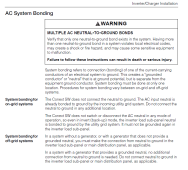
More importantly, the Schnider install guide has this:

1641767984875.png

That tells you everything you need to know about how it deals with the NG bond. From this information and knowledge of grounding and bonding, you can design a system correctly.

I wish all the inverters provided this level of clarity!!!

Also note the sentence

"The Conext SW does not switch or disconnect the AC neutral in any mode of operation, so even in inverter (Back-up) mode, the inverter load sub-panel neutral is bonded to ground by the utility grid system."
This tells us the input neutral and output neutral are tied together. That is why the one example did not show a connection to the Input Nutral screw.
 
1. The 6048 does not have a well defined ground bonding point on the chassis.
On all inverters I have checked or researched, the AC-in-ground, AC-out-ground, and inverter chassis are all tied together internally. Once AC-In-ground is connected to the grounding system, the inverter chassis is grounded. Consequently, there is no real need for a separate case ground lug.

I have little/no doubt the MPP is the same.
If the inverter's equpiment grounding conductor is connected to the system's dc negative busbar the rest of the system can be "planet referenced" via the inverter.
 
More importantly, the Schnider install guide has this:

View attachment 79028

That tells you everything you need to know about how it deals with the NG bond. From this information and knowledge of grounding and bonding, you can design a system correctly.

I wish all the inverters provided this level of clarity!!!

Also note the sentence


This tells us the input neutral and output neutral are tied together. That is why the one example did not show a connection to the Input Nutral screw.
A few things.

1. I checked with MPPSolar support regarding neutral-ground bonding and they wrote back saying:

Hi Victor

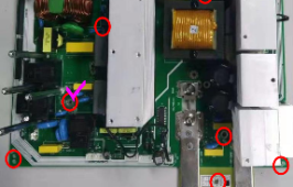
Based on the original design, when unit works in battery mode, the AC output N-G terminal will be short. When this unit works in the line mode, the N-G terminal will be open.

If you would like to unbind the AC output N-G terminal, you can remove this screw on the main board.

1641830501224.png

I hope it help you.

Thank you.

Best regards,
Andy Y. ¦ Support Team, MPP Solar Inc.

support@mppsolar.com ¦ www.mppsolar.com

2. Also contacted Schneider support and they indicated that there is indeed internal neutral bonding, and that there is NO internal NG bonding ever, no matter in grid tie state or inverter/battery state. Also, both the diagram on page 24 and the larger one in the back of the manual are correct. They use input neutral when the AC box is missing due to the absence of the neutral bus in the AC box.

3. So if you want the 6048 to behave more like an SW4048 you would need to force the neutral to float. That would be achieved by taking out the screw on the main board. Fortunately, even though the image does not show it, there is a plate over the board with a punched hole directly over the screw. You would need to use a magnetic driver is ease down and remove the screw. If you lose the screw you would have to take the plate off, not that hard.
 
Last edited:
3. So if you want the 6048 to behave more like an SW4048 you would need to force the neutral to float.
The SW4048 has a common neutral on the input and output. That means the output AC circuits are still covered by the NG bond that is in the house main breaker. The 6048 appears to isolate the neutral when in invert mode and therefore the output AC circuits will have no N-G bond while in invert mode if you disable the dynamic bonding.
 
The SW4048 has a common neutral on the input and output.
IMHO..... All inverters sold in the US should either have a common Neutral like the Schnider or dynamically generate a bond on the output when in inverter mode.
 
On all inverters I have checked or researched, the AC-in-ground, AC-out-ground, and inverter chassis are all tied together internally. Once AC-In-ground is connected to the grounding system, the inverter chassis is grounded. Consequently, there is no real need for a separate case ground lug.

I have little/no doubt the MPP is the same.
I think the NEC requires a seperate ground connection to any metal electrical box no matter if it is a passive or active enclosure.
Honestly the whole center tapped split phase USA power supply is a hot mess but we are too far down that road to do anything about it now.
 
Attached is the layout for a Generac 10KW generator that an electrician wired some years back. The generator's neutral floats and the ground is bonded to a ground rod. A transfer subpanel next to the main panel is fed by both the generator and a main panel 40 AMP 2 pole breaker through a relay. Neutrals and hots bond to busbars in the main panel. Since the main panel is the point of first disconnect the busbars are bonded. There are neutral and hot feeds from the main panel to the generator panel. The essential branch circuits have neutrals and grounds terminated to the main panel busbars, and the hots are fed to breakers in the generator panel. My wife and I wired the house and main panel well before we had the Generac installed. Generator works, but noisy as hell and needs constant maintenance.

See GENERATOR.pdf

Any reason the LV6048 cannot be a drop in replacement for the generator after bypassing the relay, with all else staying in place. The 6048 functions in bypass mode and battery mode. It comes wired with the neutral and ground bonded on the output side when in battery mode, but bonded in bypass mode unless a screw is removed on the main board. See above remarks in thread by Andy from MPPSolar.

See INVERTER.pdf

Question: any reason this won't work. If good, should the screw on the main board be removed to unbond the output neutral and ground?

Comments are much appreciated.
 

Attachments

  • INVERTER.pdf
    243.8 KB · Views: 63
  • GENERATOR.pdf
    176.4 KB · Views: 33
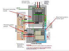
From Post # 11 of this thread, I conclude the LV6064 is not designed to have a connection between the input neutral and output neutral.

Therefore, the following changes need to be made to the 'inverter' diagram.

1) The neutral between the inverter panel and the main panel should be removed.
2) The neutrals for all the loads connected to the inverter panel should be disconnected from the main panel and reconnected to the inverter panel.
3) Unrelated to post 11: The grounds of the inverter are all tied together internally, therefore there is a ground loop that should be broken by either 1) removing the ground wire from the inverter output to the inverter panel or 2) removing the ground connection between the main panel and inverter panel. (I would prefer #1)

1642401821964.png

Also, Do NOT disable the dynamic bonding by removing the screw mentioned in post 11.

When the inverter is in pass-through mode (Powered by the main panel) the loads will 'see' the N-G bond in the main panel.
When the inverter is powered by the battery, it will internally create an N-G bond that the loads will 'see'.
 
Any reason the LV6048 cannot be a drop in replacement for the generator after bypassing the relay, with all else staying in place.
Just one more observation.

Every inverter is different. As mentioned above, the lv6048 needs several changes to the system. However, the Schneider SW4048 that was discussed earlier in the thread has a different design and could be dropped in much like your diagram shows. For the the Schneider SW4048 the following two changes would be needed:

Remove the output ground from the inverter. (Just like the LV6048). This breaks the ground loop that is in the current design.
Remove the output neutral wire from the inverter to the inverter box. (Neutral is already connected via the main panel. Connecting it to the inverter output will create a loop that can have bad RFI Side effects)

The neutrals for the loads can be left alone.
 
Attached is the layout for a Generac 10KW generator that an electrician wired some years back. The generator's neutral floats and the ground is bonded to a ground rod. A transfer subpanel next to the main panel is fed by both the generator and a main panel 40 AMP 2 pole breaker through a relay. Neutrals and hots bond to busbars in the main panel. Since the main panel is the point of first disconnect the busbars are bonded. There are neutral and hot feeds from the main panel to the generator panel. The essential branch circuits have neutrals and grounds terminated to the main panel busbars, and the hots are fed to breakers in the generator panel. My wife and I wired the house and main panel well before we had the Generac installed. Generator works, but noisy as hell and needs constant maintenance.

See GENERATOR.pdf

Any reason the LV6048 cannot be a drop in replacement for the generator after bypassing the relay, with all else staying in place. The 6048 functions in bypass mode and battery mode. It comes wired with the neutral and ground bonded on the output side when in battery mode, but bonded in bypass mode unless a screw is removed on the main board. See above remarks in thread by Andy from MPPSolar.

See INVERTER.pdf

Question: any reason this won't work. If good, should the screw on the main board be removed to unbond the output neutral and ground?

Comments are much appreciated.
This should really have been wired with a transfer switch ahead of the main panel.

Take a look at the transfer switch portion of the diagram in this post: https://diysolarforum.com/threads/mpp-lv6548-ac-wiring-question.28655/post-344268

A main panel is where utility power comes in, this is then wired to a transfer switch which allows a disconnect between grid power and any inverter or generator. This is how my pole for my acreage is wired, one main panel at the meter with breakers to each building. The main panel there is the bonded N-G and the only one. From there, a EGC is run with the L and N wires to a panel in each building. Those panels are never bonded. You simply run a EGC to each panel on a busbar and EGC to each circuit.

You would be much better served by taking your current main panel and either adding a different main panel (N-G bonded) ahead of it where it feeds a transfer switch which then feeds your current main panel (not bonded) or installing a transfer switch between your current main panel (which would be N-G bonded) and generator panel which would be a subpanel. I do not care for the current wiring where the L is fed back into the main panel and the N is in the main panel for the generator powered circuits either. Treat each part seperate as a subpanel, I'm certain the way it is currently wired is not allowed under NEC. While the LV6048 has a transfer switch built in with pass thru, if you want to work on the inverter or have to shut it down, you won't be feeding power to the subpanel which is the current generator panel. With a manual transfer switch, you simply throw the switch and can work on the inverter and not lose power to the panel which I assume is critical loads.
 
Back
Top