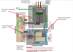
Interesting. There are other diagrams from Schneider that only show one side hooked to neutral. Since the Schnider has a hard connection between the input and output neutral, the two connections are redundant and create a loop. Personally, I would prefer to only hook one of the two up to avoid a loop that could create RFI problems.
That is correct. The schnider never switches disconnects the input neutral from the output neutral. Consequently, the output always 'sees' the N-G bond that should be in the utility panel.
The purpose of the N-G bond is to provide a low impedance path from neutral and ground so that in the event of a short between hot and ground there will be a high current to clear a fault between Hot and ground.
View attachment 80225
Let's look at a fault in the Schnider system above
View attachment 80234
The purple dashed line shows the fault path for the current needed to pop the breaker due to the fault.