diy solar

diy solar

LV6048 output neutral-ground bonding?

It may not be a NEC requirement, however you missed one important point. If the N-G bond occurs in the main panel and the inverter is powering the loads, the N-G bond will be a ground fault and trip the breaker on the inverter as it is the source, not the main panel.

This is why the neutrals should be in the subpanel after the inverter and not in the main panel.
The conversation has gotten confusing and it is not clear who is referring to what diagram.

I go back to my previous rules and notes:

1) If the AC power source (The inverter) has a Neutral-Ground bond, it is a separately derived source and a transfer switch between it and a utility must switch neutral.
[In this case, leaving the neutrals on the main panel would be a problem]

2) If the AC power source does not have a Neutral-Ground bond, it is NOT a separately derived source and a transfer switch between it and a utility must NOT switch neutral.
[In this case, leaving the neutrals on the main panel would *not* be a problem. However, see the note below about the complication of having the grid power as an input on the transfer switch and on the input of the inverter/charger.


Note 1) Where things get complicated is when the utility is on the input of the inverter, there is no N-G bond created in the inverter, and there is a transfer switch that selects between the inverter output and the utility. Since there is no N-G bond the rule would say that you should not switch neutral, but that ends up with the inverter input-neutral tied to the inverter output neutral.....and the documentation for a lot of the lower end inverters does not say whether this is acceptable or not. Inverters that generate an N-G bond when in invert mode are intended to have separate neutrals, but some of them can operate with a common neutral.

Note 2) MPP provided a way to disable it's internal bonding relay, but I have not seen anything from them that says tieing the input and output neutrals together is acceptable. I sent MPP a question about common neutral but have not heard back from them (See post 54). I pinged them again yesterday but I do not know if I will ever hear back. (Part of the delay may be due to Chinese new-year)

Note 3) On at least the older versions of the 3K Growatts, Growatt has said hooking the input neutral and output neutral together is the proper way to do it. (In this case, leaving the neutrals in the main breaker panel would work). The newer 3K growatts have an internal bonding relay and I do not know if there is a supported way of disabling the relay. Assuming there is a way to disable the relay, I also do not know if growatt would support connecting the input and output neutrals on the newer 3K units.

Note 4) On the Schnider and Solark inverters, the input and output neutrals are tied together internally. In this case leaving the neutrals on the main panel would work fine.
 
It would depend on the ground screw, some ground screws are for grounding the inverter case. It will operate, however it may not clear a ground fault of the case. The reason why is current always returns to the source, whether it is grid or the inverter.

Now, as far as removing a screw and having a floating neutral, it would depend again on the screw and where the relay bonds N-G when in inverter mode. The question becomes why you would want a floating neutral? Having a floating neutral from source will not allow a ground fault to to clear and trip the breaker.

I would not remove any screws.


One needs to know the path back to source. And which source you are coming from and if N-G are bonded.


Are you running this in some type of big loop?


Correct. When in bypass mode the inverter relies on the main panel N-G bond.


When in battery mode, the source is the inverter and N-G bond occurs in the inverter. Unless you modify the unit so it doesn't. But again, why would you?


I'm trying to understand why you want to bypass the N-G bond controlled by the inverter when in battery mode and the inverter is powering the loads.

When under AC power, the unit will not be N-G bonded internally and relies on the N-G bond at the main panel before the unit. When in inverter mode and inverter is powering the loads, the unit bonds N-G which is at the source.

You need 2 panels, one before the inverter and one after. The first panel from grid is N-G bonded, this panel is referred to as main service panel. The second panel after the inverter is not N-G bonded, it is considered a subpanel.
Does then utility grid transformers use a bonded neutral prior to the main panel?

There are many home generators that use a floating neutral for "emergency" power of the home through a generator inlet plug. This is due to the different mechanics of the generator motor design and function.
It's my understanding that the neutral is bonded within the main panel as the utility does not bond neutral and ground prior to coming into the main panel...
This enables the main panel and its N-G bond to function as intended when using a standard floating neutral home generator.
 
The conversation has gotten confusing and it is not clear who is referring to what diagram.

I go back to my previous rules and notes:

1) If the AC power source (The inverter) has a Neutral-Ground bond, it is a separately derived source and a transfer switch between it and a utility must switch neutral.
[In this case, leaving the neutrals on the main panel would be a problem]

2) If the AC power source does not have a Neutral-Ground bond, it is NOT a separately derived source and a transfer switch between it and a utility must NOT switch neutral.
[In this case, leaving the neutrals on the main panel would *not* be a problem. However, see the note below about the complication of having the grid power as an input on the transfer switch and on the input of the inverter/charger.


Note 1) Where things get complicated is when the utility is on the input of the inverter, there is no N-G bond created in the inverter
Not utilizing the AC input would seem to be safe for use with the "screw removal" method posted earlier.
 
Not utilizing the AC input would seem to be safe for use with the "screw removal" method posted earlier.
correct.

Does then utility grid transformers use a bonded neutral prior to the main panel?
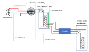
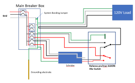
Yes, but here in North America, the utility does not rout a ground wire to the service entrance. Therefore a N-G bond is required at the service entrance in order to re-establish a low impedance fault path. It will look something like this:

1644729071033.png

In the above diagram, the LV6048 works fine without modification.

* When in pass-through mode, the fault path goes back to the main bonding jumper.
* When on battery, the lv6048 creates a new N-G bond for the fault path.

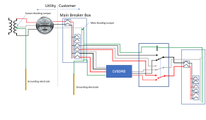
If a neutral-switching transfer switch is added before the critical loads box, everything continues to work correctly.

1644735732400.png
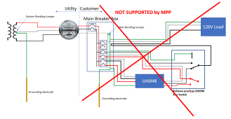
Where things could start to get wonky is if a transfer switch that does not switch neutral is used:

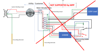
EDIT: I received notification from MPP that they do NOT support configurations where the input and output neutrals are tied together.

1644870471608.png
In the above diagram, I show the Reliance Pro/tran 310CRK (but with only 2 circuits). I also show the neutral wiring as per the 310CRK instructions.
There are two possible problems with this layout.
1) The LV6048 AC-In neutral has a hard connection to the AC-Out neutral. I do not know if the LV6048 can support this (that is what my email to MPP is asking)
2) The LV6048 will normally create an N-G bond when in battery mode. With the above layout, that would be a 2nd NG bond, and that is a problem. This issue can be resolved by removing the screw that enables the N-G bond.
 
Last edited:
Perhaps another method for the MPP without modification of the screw, would be to run the hots and neutral to the inlet supplying the main panel panel and supply a seperate ground rod for the inverter ground. This would mirror what the utility does, and some home generators utilize this method as well.
Schneider and Solark must be setup in a similar fashion, but don't use their own dedicated ground?

Basically I see all of this as a way to not have to install an entirely new critical loads panel, breakers, wiring etc, for use within a grid down situation only, which is rare. Utilizing properly pre installed generator inlet, much like Philatio is doing, with the exception of also trying to simultaneously use the AC input/pass thru feature, which definitely causes issue, as most home ICE generators do not.

Thanks for the diagrams! So useful to visualize and understand what's going on.

I'm interested what Philatio will come up with to make it all work!
 
  • Like
Reactions: Rho
Perhaps another method for the MPP without modification of the screw, would be to run the hots and neutral to the inlet supplying the main panel panel and supply a seperate ground rod for the inverter ground. This would mirror what the utility does, and some home generators utilize this method as well.
Schneider and Solark must be setup in a similar fashion, but don't use their own dedicated ground?
In general, running multiple grounds is a bad idea, but before I comment further, could you please provide a diagram of what you are describing?

Schneider and Solark must be setup in a similar fashion, but don't use their own dedicated ground?
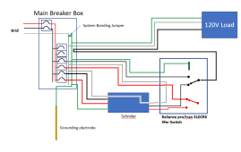
Schneider and solark tie the input and output neutral together internally and they never try to create an NG bond. Consequently, you don't need or want an neutral switching transfer switch. It would look like this:

1644735868285.png
However, that creates a loop on the neutral line so I would do it like this:

1644734945297.png
 
Last edited:
I apologize for the lack of a diagram. I have yet to learn the digital diagram tools that you're using. I'll be utilizing this tool in the future for my own system on a seperate thread and of course for better communication.

In your diagram showing the schneider i see no neutral switching. I do know that switching the neutral over would be an SDS from earlier posts and thus would require a separate grounding electrode (NEC 250.30(A)). If no neutral switching occurs than, the NG bond remains at the main panel for inverter use only on the schneider. The only grounding of the schneider occurs on its frame to the main panels ground.
Interested to see if MPP has an answer to your question.
 
I do know that switching the neutral over would be an SDS from earlier posts and thus would require a separate grounding electrode (NEC 250.30(A)).
I don't think NEC250A requires an additional grounding electrode. Unfortunately, the extreme over-use of the term 'ground' to mean many things makes this all very confusing. NEC 250(A) talks about a 'grounded' separately derived system.... and I am pretty sure that in this context 'grounded' means that there is an N-G bond creating a grounded neutral.

If no neutral switching occurs than, the NG bond remains at the main panel for inverter use only on the schneider.
I am not sure what is meant by "only on the Schnider". In the case where there is no neutral switching, the Main System Bonding Jumper in the main breaker box provides the NG bond for all situations and the inverter should never create an N-G bond. At any point in the system, if there is a short between hot and the ground wire, the Main System Bonding jumper will create a low impedance path for a large current to flow and pop a breaker. (This is called clearing the fault)

Interested to see if MPP has an answer to your question.
So am I friend, so am I!
 
I have yet to learn the digital diagram tools that you're using.
I just use Microsoft Powerpoint. Google Slides is a free equivalent.

I find it easy to whip out a simple block drawing with it..... but I have been using it since its first release.

The other thing that makes it easy for me is that I have a file with all the drawings I post here. Most of the time I can cut and paste from some previous drawings as a start for what I am wanting to draw this time (I rarely start from scratch)
 
I don't think NEC250A requires an additional grounding electrode. Unfortunately, the extreme over-use of the term 'ground' to mean many things makes this all very confusing. NEC 250(A) talks about a 'grounded' separately derived system.... and I am pretty sure that in this context 'grounded' means that there is an N-G bond creating a grounded neutral.


I am not sure what is meant by "only on the Schnider". In the case where there is no neutral switching, the Main System Bonding Jumper in the main breaker box provides the NG bond for all situations and the inverter should never create an N-G bond. At any point in the system, if there is a short between hot and the ground wire, the Main System Bonding jumper will create a low impedance path for a large current to flow and pop a breaker. (This is called clearing the fault)


So am I friend, so am I!
And there should be a comma. "for Inverter use only, on the schneider"

From what I understand about SDS, a ground is required as specified in 250.30(A)(2)(a) or (b). Not necessarily a seperate grounding device, as it can be tied into the code compliant existing ground system by way of exothermic weld, irreversible compressions, or copper buss bar screw type terminals.
 
Not utilizing the AC input would seem to be safe for use with the "screw removal" method posted earlier.


The system would work, however any ground fault in the inverter and it's case, plus the Reliance 310 would not clear a ground fault. The reason why is that portion of the system doesn't have a ground fault return path back to source if the screw is removed. MPP should have plainly stated that N-G are bonded under inverter power and N-G are not bonded under bypass. It's a safety issue, one that should remain as the system was engineered. They should never have said to remove a screw, huge liability, if it was a US company.

There are 2 choices here, one, the Reliance is considered a subpanel and powered thru the inverter which would need to be switched on all the time. That requires hard wiring. Two, install a 3 pole double throw transfer switch with neutral switched before the Reliance 310. In this case, the Reliance 310 isn't suited for the requirements needed for a safe installation due to the neutral is not switched.

Any other hodgepodge redneck engineering results in a system with unsafe conditions.
 
Last edited:
Perhaps another method for the MPP without modification of the screw, would be to run the hots and neutral to the inlet supplying the main panel panel and supply a seperate ground rod for the inverter ground. This would mirror what the utility does, and some home generators utilize this method as well.

Won't work. The ground fault detected that trips the breaker in inverter mode is due to the N-G bond in the main panel.

You can add all the ground rods you want as Mike Holt states, but it won't do any good.

Any inverter that bonds N-G when in inverter mode will trip due to the ground fault caused by N-G in the main panel. This is why those inverters have a pass thru transfer switch built in. It is designed to have power pass thru when it is desired to power from the grid. When the inverter mode is used, it is designed to provide N-G bond at the source.


Schneider and Solark must be setup in a similar fashion, but don't use their own dedicated ground?

I have no idea why Schneider and Solark keep coming into the discussion at hand as this thread is about the LV6058 inverter and basically any inverter that bonds N-G under inverter power. All that does is continue to confuse the member that is having a ground fault using a LV6048 with a Reliance 310 that has a breaker trip. It doesn't help the situation.

Basically I see all of this as a way to not have to install an entirely new critical loads panel, breakers, wiring etc, for use within a grid down situation only, which is rare. Utilizing properly pre installed generator inlet, much like Philatio is doing, with the exception of also trying to simultaneously use the AC input/pass thru feature, which definitely causes issue, as most home ICE generators do not.

It is the wrong transfer switch for the application. It was designed to be used with a floating neutral generator used in an emergency situation where grid power is down.
 
Zwy said said:
It is the wrong transfer switch for the application. It was designed to be used with a floating neutral generator used in an emergency situation where grid power is down.

I have an Eaton CH10GEN5030SN waiting in the wings. This allow for both SDS & Non SDS scenarios.

With a switched neutral, does that not create an issue at the AC input?
There is no NG bond to be compensated for when in bypass mode.
 
I have an Eaton CH10GEN5030SN waiting in the wings. This allow for both SDS & Non SDS scenarios.

Here is a link for the manual. https://www.eaton.com/ecm/groups/public/@pub/@electrical/documents/content/ct_253031.pdf

Wire as a SDS system. This is a 3 pole panel and neutral will be switched.

With a switched neutral, does that not create an issue at the AC input?
There is no NG bond to be compensated for when in bypass mode.
When the inverter is on and the Eaton transfer switch is switched to generator mode, then neutral will be switched, thus the N-G bond will be at the inverter.

This is the type of panel you need. 3 pole with switched neutral.
 
Won't work. The ground fault detected that trips the breaker in inverter mode is due to the N-G bond in the main panel.

You can add all the ground rods you want as Mike Holt states, but it won't do any good.

Any inverter that bonds N-G when in inverter mode will trip due to the ground fault caused by N-G in the main panel. This is why those inverters have a pass thru transfer switch built in. It is designed to have power pass thru when it is desired to power from the grid. When the inverter mode is used, it is designed to provide N-G bond at the source.


I have no idea why Schneider and Solark keep coming into the discussion at hand as this thread is about the LV6058 inverter and basically any inverter that bonds N-G under inverter power. All that does is continue to confuse the member that is having a ground fault using a LV6048 with a Reliance 310 that has a breaker trip. It doesn't help the situation.


It is the wrong transfer switch for the application. It was designed to be used with a floating neutral generator used in an emergency situation where grid power is down.
Yes! I understand what you're saying. The schneider and solark was brought up prior to joining the thread, so I was just comparing that some of the methods relating to how things CAN be hooked up will work in situations with different equipment. I'm not advocating adding any seperate ground rods, but in the case of an SDS system, that system is required to be grounded by certain methods through the homes ground system which is outlined in the NEC 250.30(A)(2)(a) or (b) section of code. I'm not advocating hodgepodge methods of course, I have been saying from the beginning here that removing the screw is not something I would do.
In the situation of Philatio, it does sound like without a 3 pole neutral switching transfer switch creating an SDS. At least for generators, Article 250.20(B) of the 2020 NEC sets forth requirements for grounding alternating current systems where transformers supply 50 to 1000 Volts. In addition, Article 250.30 sets forth requirements for grounding separately derived systems, which is first defined in Article 100. Not sure if these grounding requirements apply to an inverter setup in this way.

Ground fault detection is required for an ungrounded system common to the LV6048 and its N-G bond.

Its sufficient to say the manufacturers and their different methods of dealing with the issues at hand are changing and evolving, but knowing what you want to do and what the equipment is capable of and why would be pertinant to understanding what one really needs for their specific use case for integration into what they have.
 
Here is a link for the manual. https://www.eaton.com/ecm/groups/public/@pub/@electrical/documents/content/ct_253031.pdf

Wire as a SDS system. This is a 3 pole panel and neutral will be switched.


When the inverter is on and the Eaton transfer switch is switched to generator mode, then neutral will be switched, thus the N-G bond will be at the inverter.

This is the type of panel you need. 3 pole with switched neutral.
Maybe I didn't explain myself well enough.

The CH10GEN5030SN will allow me to, if I understand correctly, run the transfer switch circuits off the inverter, and also still run the circuits in the main panel that are NOT part of the transfer switch. In other words, run them simultaneously.

If I am correct, then I would like to charge up the batteries VIA AC from the main panel from one of the dedicated circuits that is not part of the transfer switch.
 
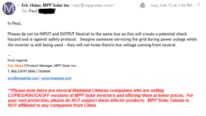
Folks, I just heard back from MPP:

hi Paul,

Please do not tie INPUT and OUTPUT Neutral to the same bus as this will create a potential shock hazard and is against safety protocol. Imagine someone servicing the grid during power outage while the inverter is still being used - they will not know there's live voltage coming from neutral.
--
Kind regards
Eric Hsiao |
Product Manager, MPP Solar Inc.
T: 886.2.8797.8896 | TAIWAN
I do not follow his reasoning, but the bottom line is that MPP does not support connections between the input and output neutral.

So.... In the configurations we have been talking about with the LV6048 a transfer switch must switch the neutral

1644810576874.png


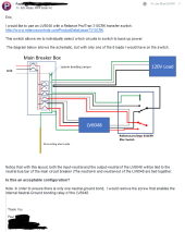
Here is an image of my email to MPP followed by an image of the response
1644871421310.png


The Response

1644871132875.png
 
Last edited:
Switch neutral. Forget about the AC input pass thru or battery charging. Buy a seperate battery charger and run invert mode....derp
 
MPP should have plainly stated that N-G are bonded under inverter power and N-G are not bonded under bypass. It's a safety issue, one that should remain as the system was engineered. They should never have said to remove a screw, huge liability, if it was a US company.
Where and when have MPP given this advice ?
I only know of this fudge from Growatt discussions.
 
Yes, but here in North America, the utility does not rout a ground wire to the service entrance.
Not strictly true, the bare wire the other 2 line wires are attached to between poles and strung to your house are grounded at every pole and are the ground/neutral wire to the house. It is one and the same. This serves the desired effect for the PoCo, keeps their system safer from lightning and provides the split phase bullcrap we have backed ourselves into a corner with.
Now the wires are attached to your house, the NEC gets involved and want's it's own things done to protect you, the home dweller. So they want another ground rod bound to the neutral at the service entrance (meter or breaker panel) and then totally split them throughout the home, because the neutral needs to carry current and the ground specifically goes not unless there is a fault.
Have I ever mentioned how fucked up the USA split system is ??? It baffled the shit out of me when I moved here from England 30 years ago.
 
Back
Top