EastTexCowboy
Solar Wizard
For those of you who are running split phase MPP LV6548 inverters and LiFePO4 batteries, I'm curious on how you have configured your AC input settings. There seems to be multiple opinions on this.
There is multiple people on here much smarter then me in that regard. But I’ll tell you what I did. I have a rack and dyi batteries. I had the inverters set to 48vs and it triggered a voltage warning on the inverter. So I set it at 50 and it was taking my batteries to around 10%. So I settled on 51v. Usually is around 15% when it switches over. The only time this gets problematic is with a huge inductive load. Which can make the voltage sag even if you have plenty of juice left. But that only applies if you have a small battery bank.Both would be fine, I suppose, but I was curious about cutoff voltage parameters. I'm thinking most people who have all three sources would use the S6U setting, or solar/battery/utility. I realize there can be reasons for doing otherwise but that seems like it would be the most common. The cutoff voltage is where I see multiple opinions.
Appreciate the feedback.There is multiple people on here much smarter then me in that regard. But I’ll tell you what I did. I have a rack and dyi batteries. I had the inverters set to 48vs and it triggered a voltage warning on the inverter. So I set it at 50 and it was taking my batteries to around 10%. So I settled on 51v. Usually is around 15% when it switches over. The only time this gets problematic is with a huge inductive load. Which can make the voltage sag even if you have plenty of juice left. But that only applies if you have a small battery bank.
Hope that didn’t just seem like rambling. My advice is try it out. The same with the back to solar voltage. Check your SOC and set it that way. I settled on 54v to return to solar.
You should be fine then. If it’s rack batteries then the 51v should get you down to the alarm light on them. ? if it does don’t panic. It’s just a warning. That goes away when they get to around 40% state of charge. Anxious to see your setup. When it’s finished don’t forget to post some photos. Or maybe you are finished and I just haven’t seen them.30kWh

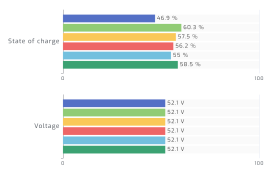
It depends on what type of batteries you have. With EG4 racks you can lead the negative from the bottom of the rack and positive from the top to help mitigate some of that. If they are running in parallel they will always share the same voltage. They’ll eventually become more balanced over time . If it doesn’t balance quickly enough for you, can can always charge it up to 100% on its own then introduce it to the pack when they are full also.I'm mostly finished. I'll post some photos. I'm still doing some testing before I throw a bunch of load on it. Right now I've got the PV input shut off and running a 1300w electric heater just to drain it slowly and see what happens. I just looked and the batteries aren't as close as I expected in SOC. I've seen this before but they usually leveled out before now. It seems a little strange because the battery voltages are the same but evident the BMS on battery #1 is reporting a lower SOC than the others. Any thoughts?
View attachment 134103
Yeah, that's how I have the positive and negative connected to the battery array. I charged all of them up separately when I got them but I could do that again. I've actually had this system running for a few months now with a light load but I tore it down again to add my transfer switch and tie in the AC input. I still have a little cleanup to do on some of the wiring and I have to terminate all the wires coming into the subpanel to add the rest of the circuits for the load.It depends on what type of batteries you have. With EG4 racks you can lead the negative from the bottom of the rack and positive from the top to help mitigate some of that. If they are running in parallel they will always share the same voltage. They’ll eventually become more balanced over time . If it doesn’t balance quickly enough for you, can can always charge it up to 100% on its own then introduce it to the pack when they are full also.

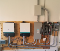
That’s a nice clean setup. I saw one similar on YouTube. May have even been you.Yeah, that's how I have the positive and negative connected to the battery array. I charged all of them up separately when I got them but I could do that again. I've actually had this system running for a few months now with a light load but I tore it down again to add my transfer switch and tie in the AC input. I still have a little cleanup to do on some of the wiring and I have to terminate all the wires coming into the subpanel to add the rest of the circuits for the load.
View attachment 134104
Thanks. No, not mine on YT. I've redone it a couple of times because I didn't like the way it looked. This last time my wife told me not to glue any of that conduit because she knows I'm gonna change something again.That’s a nice clean setup. I saw one similar on YouTube. May have even been you.
I wish I had a wire way also. Check out Watts247 for his 200 amp dc breakers. They are nice. The ones you have technically I believe only go to 48v. So you could have some issues if there were ever a problem. Since the nominal voltage of the batteries is 51v. I have them in the center in my later videos. Easy to spot. I have panels everywhere also. That’s the way to go for winter. Btw I’m certainly not critiquing. Yours is so much cleaner then mine. HahaThanks. No, not mine on YT. I've redone it a couple of times because I didn't like the way it looked. This last time my wife told me not to glue any of that conduit because she knows I'm gonna change something again.
Looking back I wish had put a metal wire trough and conduit down to it from each device. Those look really nice. But all things considered I'm pretty happy with it. I have 16 panels running and another 16 in the shop waiting for me to get a couple friends to come help me get them installed on the shop roof. I know that's over paneled but it will help some in the winter. I should do a post one of these days about the roof access hatch I put in my shop so I don't have to climb a 20' ladder to access the panels.
I just went and watched one of your videos on YT. Good work. I'll watch the rest of them as well.
Haha. It is so addicting though. I can say I’ve never actually be so interested in any other hobbies like I am with solar. You should try a diy. It’s actually easy. Just need a place to put them. Those are deep sea breakers for your batteries though right? I had ones like it but I got worried after I saw the voltage limit. I guess the T class fuses technically take care of anything catastrophic.I saw those Watts247 breakers you have for your battery feed. Nice! I actually have a 300A T-class fuse on mine. The breakers in the box on the left are for the panels and are 63A 500V. I have an outside AIMS disconnect for the panels as well, but I put the breakers in line inside so I would have a quick way to turn them off should the need arise.
I like the way you split the battery feed using the Watts247 breakers. I'm going to keep that in mind when I add more batteries, and you know I'll be adding more batteries. I mean, how can you not? ? I'm envious of your battery setup too. Mine are six of the EG4 Lifepower from SS. I'm going to have to decide if I'm willing to mess with a DIY solution like yours or just spring for the extra money and get another six rack batteries.
I'm not addicted or anything. I can quit anytime I want.
I’ve heard mixed opinions on here about Docan power. But that’s where I bought my cells for the diy batteries. They came in great condition and no issues. I ordered through Jenny Wu. Those with a nice bms is around $2,500 for 280ah battery. So you save around 30% usually I think over a rack battery. But there is something to be said for warranties also I guess. I wanted more storage. And also wanted to know more about how everything works. Seems as if I can’t really fully learn unless I actually do it with my own hands. If you get a jkbms the balancing is super nice. But my overkill bms works great also.Now I know which breakers you are talking about. Duh. Sorry. Those are 150A each. A little undersized based on some discussions here on the forum, but if they start tripping I'll look at changing them. I've gotten mixed opinions from the gurus but the general consensus was they should be fine. So I have the T-class fuse from the battery bank and the feed to each inverter has a 150A breaker.
I keep thinking I may do a DIY battery. I need to get the current setup completely finished and let it run a bit first. My wife has been on me a little to go ahead and by another rack of server batteries but I'm holding out so far.


