diy solar

diy solar

LV6548 Critical Load Schematic Check

bertiojones

New Member
Joined
Feb 14, 2022
Messages
90
(Moved to appropriate forum area)

Hi all!

Looking for some feedback on this build before I start spending money.

Couple of things to explain out the gate. I have DC Disco and AC Disco to help with passing inspection. Inspectors love quick safety disconnects with signage otherwise I would just be using a combiner with breakers as the disconnect. (Should I still use a breaker/combiner box for protection?)

Also I will be using a switched interlock on the Critical Load Panel to bypass the Inverter for maintenance and feed grid back to that panel. The Interlock is UL listed by Eaton. Critical Load Panel will be 1 foot to the right of the main panel and have loads extended into it. Loads will be everything in my house minus large loads like dryer and A/C (for now)

Three biggest things I am unsure of...

1) Panels sizing. Running 4 strings seems silly for 7.12kw of solar but running all 4 MPPT's and having less panels seems like the way to go cost wise. Less panels, less racking (Will be roof racked). I am seeing that 250 VOC on the LV6548 is an odd spot for panels and that 320 watt panels are a sweet spot. But even then now your adding another 6 panels for the same amount of solar and increasing your amps and therefore wiring gauge. So to me it seems odd but my math checks out so let me know if I am missing something. It would be nice not to use up all 4 MPPT's in case I wanted to expand but I guess thats what a separate MPPT on the battery is for.

2) The runs will be Main Panel - 50 feet - Inverter - 50 feet - Critical Load Panel. Manual asks for 4AWG (I would run 6/3 or 4/3) for the input and output but I am reading people are barely able to get 6AWG to fit in the terminals. With my distance of 50 feet would the volt drop be high enough to warrant 4AWG? If so how would I make it fit in the terminal? I don't mind the cost I just want to do it right the first time. Either way its going to be $400-$600 in cable for both 50 foot runs.

3) Fusing on the battery. I am seeing running individual 150 amp fuses for each Inverter. My brain is thinking if I am only using EG4 batteries with their own OCP of 125 amps adding another fuse seems redundant. Tell me if I am wrong. Also I will be adding up to 6 of those batteries together eventually down the road once the system is working. The battery sizing part seems the easiest to expand as needed.

Thanks for all your time!

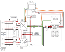
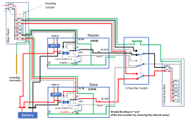
(I attached the blueprint inline and for download)
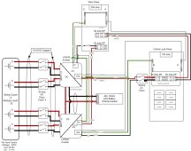
LV6548 CLP Pic.jpeg
 

Attachments

  • LV6548 CLP.pdf
    66.8 KB · Views: 20
(Moved to appropriate forum area)

Hi all!

Looking for some feedback on this build before I start spending money.

Couple of things to explain out the gate. I have DC Disco and AC Disco to help with passing inspection. Inspectors love quick safety disconnects with signage otherwise I would just be using a combiner with breakers as the disconnect. (Should I still use a breaker/combiner box for protection?)

Also I will be using a switched interlock on the Critical Load Panel to bypass the Inverter for maintenance and feed grid back to that panel. The Interlock is UL listed by Eaton. Critical Load Panel will be 1 foot to the right of the main panel and have loads extended into it. Loads will be everything in my house minus large loads like dryer and A/C (for now)

Three biggest things I am unsure of...

1) Panels sizing. Running 4 strings seems silly for 7.12kw of solar but running all 4 MPPT's and having less panels seems like the way to go cost wise. Less panels, less racking (Will be roof racked). I am seeing that 250 VOC on the LV6548 is an odd spot for panels and that 320 watt panels are a sweet spot. But even then now your adding another 6 panels for the same amount of solar and increasing your amps and therefore wiring gauge. So to me it seems odd but my math checks out so let me know if I am missing something. It would be nice not to use up all 4 MPPT's in case I wanted to expand but I guess thats what a separate MPPT on the battery is for.

2) The runs will be Main Panel - 50 feet - Inverter - 50 feet - Critical Load Panel. Manual asks for 4AWG (I would run 6/3 or 4/3) for the input and output but I am reading people are barely able to get 6AWG to fit in the terminals. With my distance of 50 feet would the volt drop be high enough to warrant 4AWG? If so how would I make it fit in the terminal? I don't mind the cost I just want to do it right the first time. Either way its going to be $400-$600 in cable for both 50 foot runs.

3) Fusing on the battery. I am seeing running individual 150 amp fuses for each Inverter. My brain is thinking if I am only using EG4 batteries with their own OCP of 125 amps adding another fuse seems redundant. Tell me if I am wrong. Also I will be adding up to 6 of those batteries together eventually down the road once the system is working. The battery sizing part seems the easiest to expand as needed.

Thanks for all your time!

(I attached the blueprint inline and for download)

View attachment 90969
1) You successfully avoided the ground loop that many folks create with this type of set-up. Good job. However, rather than bringing the ground from the AC-Out of the inverters to the critical load box. I would ground the critical load box from the main load center. The difference is small, but I like the shortest ground path possible. It also means you can remove the inverters for service or maintenance without moving the ground.

2 The AC-In neutral ends up being connected to the AC-Out neutral. Please check with MPP support on this. They explicitly said it is not supported on the 6048. (Note: I have not tried it but from what I understand, the system will still work like this. I just don't like to build configurations that are not supported). If MPP says it is not supported, the only way I know to do what you want in a supported way is to use a proper 3-pole transfer switch that also switches the neutrals.

1649804132481.png

3 I like to make sure that I keep phases consistent. If a load is getting Line 1 when the interlock is on the main panel, it should get Line 1 from the inverter that is getting powered by line one.
 
1) You successfully avoided the ground loop that many folks create with this type of set-up. Good job. However, rather than bringing the ground from the AC-Out of the inverters to the critical load box. I would ground the critical load box from the main load center. The difference is small, but I like the shortest ground path possible. It also means you can remove the inverters for service or maintenance without moving the ground.

2 The AC-In neutral ends up being connected to the AC-Out neutral. Please check with MPP support on this. They explicitly said it is not supported on the 6048. (Note: I have not tried it but from what I understand, the system will still work like this. I just don't like to build configurations that are not supported). If MPP says it is not supported, the only way I know to do what you want in a supported way is to use a proper 3-pole transfer switch that also switches the neutrals.

3 I like to make sure that I keep phases consistent. If a load is getting Line 1 when the interlock is on the main panel, it should get Line 1 from the inverter that is getting powered by line one.
1)
I completely just forgot to tie the ground in from the Main Panel to the CLP. I was planning on putting it there. I will take your advice on not running a ground back from AC-Out to the CLP. This saves me from running another wire.

2)
Are you talking about via the internal bonds in inverter? Or just my schematic makes it seem like they are connected?
If the internal bonds I've seen a lot of posts about this relay switching and bonding vs non bonding so any input on that front is appreciated.
If you are just talking about the schematic makes it seem like they are connected it might just be bad drawing.
It should look like:
The neutral to both AC In's will be connected from the same wire from the main and split 1 into 2 at the inverters.
The neutral from both AC Out's will also be bonded to their own wire 2 into 1 which will run back to the CLP's neutral bar.

3)
100% will make sure I am not mixing up phases. I will also try and load balance across phases in the CLP for 120 loads.

Really appreciate your thoughts. Let me know what you think about my solar conundrum. 7.12kW isn't nothing to scoff at and when you add up the cost of racking more panels that are a lower wattage to try and max out the PV inputs it ends up being more expensive for barely any more wattage. I am thinking when the time comes for more solar I can upgrade to newer unit or just add a charge controller to the battery bank.
 
Last edited:
...the only way I know to do what you want in a supported way is to use a proper 3-pole transfer switch that also switches the neutrals.
I see what you are saying now.

I would need to get a 3 pole switch that has On - Off - On. That way it would kill not just L1 and L2 from the main but the neutral as well.
 
I would need to get a 3 pole switch that has On - Off - On. That way it would kill not just L1 and L2 from the main but the neutral as well.
Having a center Off position is not necessary. You just need a 3-pole 2-throw switch (On-On)

1649809808370.png
 
HA of course why didn't I think about that. You just saved me about $500.

Thanks again!
Just curious what you've found so far in 3-throw and/or 2-throw 3-pole transfer switches? I came across the Siemens DTNF322 but called around and it seems like most places (in CA, anyway) don't stock them and would need to special order them with essentially an unknown lead time. Any recommendations?
 
Just curious what you've found so far in 3-throw and/or 2-throw 3-pole transfer switches? I came across the Siemens DTNF322 but called around and it seems like most places (in CA, anyway) don't stock them and would need to special order them with essentially an unknown lead time. Any recommendations?
I bought a used double throw 3 pole from a guy on ebay, I picked it up but he does ship. he was asking 350, I offered 300 and bought it.
he seems to have another here is a link. I have zero interest in the itm or seller

https://www.ebay.com/itm/334171663894?epid=1677022958&hash=item4dce2eee16:g:oIYAAOSwr3phXM5O
 
This is not necessarily related to the transfer switch, but in my setup, the outputs of two LV6548 have to run in a conduit about 15' to get to the transfer switch. I'd ideally like to bond the neutrals together closer to the inverters since that reduces the number of conductors running through the conduit. Does anyone see any issues in doing this, vs. bonding them together closer to/in the transfer switch?
 
Last edited:
I'd ideally like to bond the neutrals together closer to the inverters since that reduces the number of conductors running through the conduit. Does anyone see any issues in doing this, vs. bonding them together closer to/in the transfer switch?
I don't see a problem with it.
 
These 3 pole rotary's might be the ticket for being able to switch the neutral.

3 Pole AC changeover

$200
IP65 (Possibly equivalent to Nema4X)
3-4 pole options
63 amp max

I just need to figure out if they are ON-ON or ON-OFF-ON

It seems like they have lockout capability which would imply there is a middle selection for OFF. If so this would be perfect!
 
(Moved to appropriate forum area)

Hi all!

Looking for some feedback on this build before I start spending money.

Couple of things to explain out the gate. I have DC Disco and AC Disco to help with passing inspection. Inspectors love quick safety disconnects with signage otherwise I would just be using a combiner with breakers as the disconnect. (Should I still use a breaker/combiner box for protection?)

Also I will be using a switched interlock on the Critical Load Panel to bypass the Inverter for maintenance and feed grid back to that panel. The Interlock is UL listed by Eaton. Critical Load Panel will be 1 foot to the right of the main panel and have loads extended into it. Loads will be everything in my house minus large loads like dryer and A/C (for now)

Three biggest things I am unsure of...

1) Panels sizing. Running 4 strings seems silly for 7.12kw of solar but running all 4 MPPT's and having less panels seems like the way to go cost wise. Less panels, less racking (Will be roof racked). I am seeing that 250 VOC on the LV6548 is an odd spot for panels and that 320 watt panels are a sweet spot. But even then now your adding another 6 panels for the same amount of solar and increasing your amps and therefore wiring gauge. So to me it seems odd but my math checks out so let me know if I am missing something. It would be nice not to use up all 4 MPPT's in case I wanted to expand but I guess thats what a separate MPPT on the battery is for.

2) The runs will be Main Panel - 50 feet - Inverter - 50 feet - Critical Load Panel. Manual asks for 4AWG (I would run 6/3 or 4/3) for the input and output but I am reading people are barely able to get 6AWG to fit in the terminals. With my distance of 50 feet would the volt drop be high enough to warrant 4AWG? If so how would I make it fit in the terminal? I don't mind the cost I just want to do it right the first time. Either way its going to be $400-$600 in cable for both 50 foot runs.

3) Fusing on the battery. I am seeing running individual 150 amp fuses for each Inverter. My brain is thinking if I am only using EG4 batteries with their own OCP of 125 amps adding another fuse seems redundant. Tell me if I am wrong. Also I will be adding up to 6 of those batteries together eventually down the road once the system is working. The battery sizing part seems the easiest to expand as needed.

Thanks for all your time!

(I attached the blueprint inline and for download)

View attachment 90969
I’m doing a similar thing and is it okay that neutral is always connected from main panel to critical panel? Seems like neutral bypasses the inverters.

Do you know what happens when I move main loads over to critical loads panel? Do I have to located all the corresponding neutrals and move them over as well?
Two answers:2)

1) People report that it works just fine to have the inverter wired with a common neutral (In and out neutral connected). However if your inverter does internal Neutral-Ground Dynamic bonding, it should be disabled.
* To determine if you have internal N-G dynamic bonding, check for continuity when the unit is not connected to anything at all. If there is continuity, you almost certainly have internal N-G dynamic bonding.​
* To disable the bonding, it is usually a screw that must be removed deep inside the inverter.​
2) The documentation on the Growatt, MPP and EG4 inverters are all imply a *separate* neutral wiring should be done. I have tried to get a clear statement from all three of these companies on whether they support a common-neutral configuration but have failed to get anything from them.
The closest I have come is that Growatt has said that on the older versions of their 3k inverters that did not have internal N-G bonding you should do the common neutral configuration. I have not been able to get a statement from them about common neutral on the newer versions of their inverters.
 
Back
Top