Gooood
")
So the relay does not bond N-G in battery mode.
You know this should not cause any problem in line mode. Only when inverter goes to grid separated battery mode.
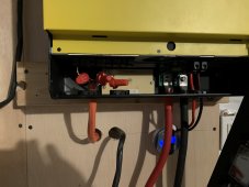
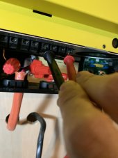
Maybe a check here between incoming G - outgoing G and incoming N - outgoing N ?
I was starting to think through and make a model in my mind about the resistor solution you proposed ... but it was to much for my processor
.
Here is where I was while stearing in a childish schematic paint pic I throw up fast :
Hmmm good question.
G is needed for reference and many reasons so there is not a good idea.
For N ... mayyyybe? If you put inverter into off-grid mode with grid support (not grid-tie) then relay should be in not bonding position (and not producing power out to grid, only load). But then can you measure the resistance between the outgoing G and incoming N ? Not a good idea?
Maybe better with resistor in incoming G and check with outgoing N ?