eabyrd
Solar Enthusiast
Yeah, you’re
What's interesting to me is that the chassis to ground potential formed when the unit is ungrounded is a DC voltage of about 18 volts. I haven't historically grounded my battery bank, but I'm going to and see what that changes (if anything).
Right now I've got the unit wired without input or output ground, but I've made sure every component up to, and after the unit is tied back to the main panel with no loops. I think, I am OK (assuming I can stop licking my finger & touching the inverter chassis just to see if it still tickles) from a fault clearing perspective since every circuit has a single fault path back around a circuit breaker, an every metal other component also has an EGC path.
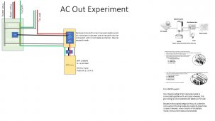
You're pretty much spot on about MPP, send us a diagram of your AC input side, take some readings across the input terminals and wait while we go dark. The seller has been good, and offered to trade me out, but I'm curious about this beast. Right now I'm asking them if the internal transfer switch also switches neutral, which it should if it's designed to form an internal neutral ground bond. The old Sigineer that I am coming from got around the neutral loop issue by only bringing in L1, L2 & G, and only outputting L1, L2, & N, but this beast chokes if you try that combination.That is strange
Without AC in connected it starts.
What did MPP say about it ?
Let me guess (again lazy to read back) ... asked for your wiring diagram ?
I remember there was an issue with the common neutral VS separated neutral. Where I said separated neutral is the good solution.
But in current case there is nothing connected on the AC out when the inverter do not start.
So there can not be a neutral backflow problem.
So ... inverter is faulty.
What's interesting to me is that the chassis to ground potential formed when the unit is ungrounded is a DC voltage of about 18 volts. I haven't historically grounded my battery bank, but I'm going to and see what that changes (if anything).
Right now I've got the unit wired without input or output ground, but I've made sure every component up to, and after the unit is tied back to the main panel with no loops. I think, I am OK (assuming I can stop licking my finger & touching the inverter chassis just to see if it still tickles) from a fault clearing perspective since every circuit has a single fault path back around a circuit breaker, an every metal other component also has an EGC path.