diy solar

diy solar

LVX6048WP F12 Ground Fault Error

brazengoat

New Member
Joined
Jan 26, 2022
Messages
8
I just finished installing my system as shown in the attached pic. Here's a quick rundown of my system.
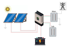
  • Two arrays of 11 Jinko 265W Class A poly panels. Each array puts out around 380V. They are both on the same ground mount about 200ft from the inverter/main panel.
  • LVX6048WP Inverter.
  • Two Jakiper 48V batteries.
solarsystem.png
I have been running the inverter and batteries without the PV arrays (just using power from the grid) for a couple of months now without any issue. I finally finished mounting my solar panels and hooked them to the inverter. Everything works just fine until I turn the grid connection to the inverter on. Within a minute or two of flipping the breaker on from my main panel, the inverter throws a F12 error, which reads: GFCI Fault. Leakage current exceeds the limit. This also happens at night while there is no voltage from the PV arrays.

According to the manual, the LVX6048WP, being a non-isolated inverter, requires that the panels are not grounded. From what I understand, that means that neither the positive nor negative wire should be connected to ground. That does not mean that the panel frames themselves should not be grounded. Am I correct in my understanding?

In trying to diagnose the issue, I've done some probing with a multimeter. Here's what I found:

While the PV array is disconnected from the inverter:
  • I get a 380V reading between the positive and negative of each array.
  • I get a 0V reading from both the positive and negative to ground.
  • I get a 40V reading from the positive and negative of the input of the inverter. When I probe from the positive to my main panel ground, I get 260V (that is with the PV arrays and the grid disconnected!)
  • While the grid is connected, if I probe from the positive of the input of the inverter to my main panel ground, it will immediately cause the F12 fault even though the PV arrays are not connected.
While the PV array is connected and the inverter is drawing power:
  • I get a 270V reading from positive to ground and a 10V reading from negative to ground
  • I get a 330V reading between the positive and negative of each array.
So the question is do I have a bad inverter, do I have something improperly wired, or is there leakage current traveling 200ft through the earth?
 
I just finished installing my system as shown in the attached pic. Here's a quick rundown of my system.
  • Two arrays of 11 Jinko 265W Class A poly panels. Each array puts out around 380V. They are both on the same ground mount about 200ft from the inverter/main panel.
  • LVX6048WP Inverter.
  • Two Jakiper 48V batteries.
View attachment 131676
I have been running the inverter and batteries without the PV arrays (just using power from the grid) for a couple of months now without any issue. I finally finished mounting my solar panels and hooked them to the inverter. Everything works just fine until I turn the grid connection to the inverter on. Within a minute or two of flipping the breaker on from my main panel, the inverter throws a F12 error, which reads: GFCI Fault. Leakage current exceeds the limit. This also happens at night while there is no voltage from the PV arrays.

According to the manual, the LVX6048WP, being a non-isolated inverter, requires that the panels are not grounded. From what I understand, that means that neither the positive nor negative wire should be connected to ground. That does not mean that the panel frames themselves should not be grounded. Am I correct in my understanding?

In trying to diagnose the issue, I've done some probing with a multimeter. Here's what I found:

While the PV array is disconnected from the inverter:
  • I get a 380V reading between the positive and negative of each array.
  • I get a 0V reading from both the positive and negative to ground.
  • I get a 40V reading from the positive and negative of the input of the inverter. When I probe from the positive to my main panel ground, I get 260V (that is with the PV arrays and the grid disconnected!)
  • While the grid is connected, if I probe from the positive of the input of the inverter to my main panel ground, it will immediately cause the F12 fault even though the PV arrays are not connected.
While the PV array is connected and the inverter is drawing power:
  • I get a 270V reading from positive to ground and a 10V reading from negative to ground
  • I get a 330V reading between the positive and negative of each array.
So the question is do I have a bad inverter, do I have something improperly wired, or is there leakage current traveling 200ft through the earth?
For one thing you're exceeding the max VOC input of this inverter by a mile. The max voc is 600v you have 2 arrays running at 380v for 760v this is absolutely wrong. On top of that, it is winter time--- not sure were you live but temperature drops can put that voc to 900v. You will destroy your inverter if you keep it like that.
Your combined array should not exceed 480v to allow for the VOC increase when the temperature drops.
Thanks for the reply. This inverter has two MPPT inputs, each of which can handle 600v, so I don't believe I have an issue there, or am I wrong?
 
Thanks for the reply. This inverter has two MPPT inputs, each of which can handle 600v, so I don't believe I have an issue there, or am I wrong?
In a word, yes. The manual doesn't help matters either. But I can tell you that if you unit had 2 600voc mppts, the brochures for them would say 1200VOC. 600v is the total for both mppts. One way you can check is either turn one array and try the unit like that, or remove a couple of panels from each array until you are at about 500v, combined and see if that makes a difference.
 
In a word, yes. The manual doesn't help matters either. But I can tell you that if you unit had 2 600voc mppts, the brochures for them would say 1200VOC. 600v is the total for both mppts. One way you can check is either turn one array and try the unit like that, or remove a couple of panels from each array until you are at about 500v, combined and see if that makes a difference.
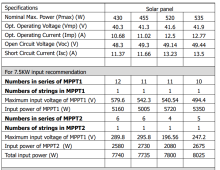
I have tried with just one array at a time and still have the same issue. The manual does show an example of having nearly 750v connected with 494.4v on MPPT1 and 247.2v on MPPT2.

manual.png
 
The table from the manual is as confusing to me today as the first time I read it. My suspicion is that whoever wrote the manual copied that from one of Voltronics inverter manuals that can have 1000vdc of pv input.
 
Let's take the total input voltage out of the question since I am testing using just one array, so just 380v input.

Maybe we can break this down one question at a time. Since this is a non-isolated system, should the panel frames be grounded to earth at the array or not?
 
To be honest I have not clue about grounding an array. There are lots of threads about that here. From what I've read the best practices are to tie your PV ground to your house ground, but again, that's just from a glancing at some of these threads. I just pointed out one thing that was wrong with your setup.
btw don't hesitate to think that your unit is defective. Might be good if you had another one to test. Or that this one of the problems with this unit. See here: https://diysolarforum.com/threads/new-all-in-one-mpp-lvx6048wp-ul-certified.23505/post-601209
 
Let's take the total input voltage out of the question since I am testing using just one array, so just 380v input.

Maybe we can break this down one question at a time. Since this is a non-isolated system, should the panel frames be grounded to earth at the array or not?
Something I thought: There is an option in the Solar Power software that says "PV Parallel" If you enable this function and it functions like I think it supposed to, then you can use both your strings you have to make sure that your combined current doesn't exceed 15amps.
 
I have parameter 37- PV Parallel disabled. I do not want my strings to be paralleled in case I have shading on one string and not the other. I talked to tech support at watts247 and they agreed that disabled is the proper setting. The inverter shows my two individual strings each at about 380v.
 
Back
Top