diy solar

diy solar

makeSkyBluer

meaCulpa

New Member
Joined
Jun 14, 2022
Messages
152
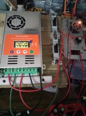
list of enhancement things that could be done to msbs and powmrs
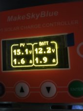
1> data logging

2>add wifi version of AdafruitQT PY so that upgrading could be done OTA


3>andriod/iFone app

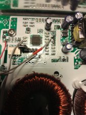
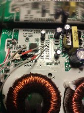
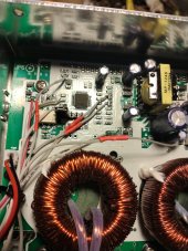
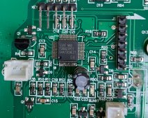
4>hardware add-on to make it synchrounous conversion.. I am working on this now..


makeSkyBluer-master2.zip is my latest version..I added dspLAST..kinda nice..and took out dspPWM_MPPT because that only works with the msb 30A model..


Attachments

  • makeSkyBluer-master.zip
    16 KB · Views: 18
  • makeSkyBluer-master2.zip
    16.1 KB · Views: 15
Last edited:
mounting the new display board and re-glue-ing the black molding in place..IMG_20220917_104111.jpg
 
PowMr PC Board connection points:

5v R30
GND C13, C14
PWM1 R67
PWM2 R66
PWM3 R89 (marked 'SPARE')
Fan D5
Temp R48 or D17
PVi C27 or D3
BATTv D7
PVv D9

MakeSkyBlue 30A:
BATTv D3
PVv D4
PVi D5
Temp D2
 
Last edited:
Steps to begin converting to the new display/micro pc board:

two screws.. after u have properly mounted the new display board and let all glue dry, mount the control panel to the left side of the msb..plug in the fan..see pics..
 

Attachments

  • IMG_20220917_134532.jpg
    IMG_20220917_134532.jpg
    219.7 KB · Views: 28
  • IMG_20220917_134546.jpg
    IMG_20220917_134546.jpg
    218 KB · Views: 29
now use a 12v power supply or a battery--doesnt really matter-- can be a small lead acid battery(what I use) or a stack of lithium 18650s, whatever..
hook up 12v --thru a switch or circuit breaker-- to the msb battv and batt gnd..make SURE polarity is correct.. dont blame me..
flip the switch ON.. if the msb is good, the fan will self-test on for several seconds..
this lets u know the msb micro is alive..now we need to parralise it with a forced master reset..
make a 1k resistor jumper from a 2-pin female SIL..
locate the ISP programming SIL port.. one end will have GND, the other will show about 5vdc..at the GND end install the 1k jumper..
now powerup 12v battv.. the fan should NOT self-test run..
U can also verify the micro is being held in reset by reconnecting the original display and observe the blank-no info- display after (no) bootup..
 

Attachments

  • IMG_20220917_135746.jpg
    IMG_20220917_135746.jpg
    140.9 KB · Views: 13
  • IMG_20220917_135910.jpg
    IMG_20220917_135910.jpg
    196.2 KB · Views: 13
  • IMG_20220917_140420.jpg
    IMG_20220917_140420.jpg
    147.6 KB · Views: 13
Next: plug in a IDC 2x7 ribbon cable to the display board and peel back all the single wires back to about 2inches from the plug on the display..
if u want to..keep the two outside pairs together in pairs.. all these (4) wires are all GND.. two each should end up soldered to two separate GND points on the msb pc board to establish good GND..
 

Attachments

  • IMG_20220917_145331.jpg
    IMG_20220917_145331.jpg
    164.2 KB · Views: 12
4 wires to GND 2 x 2.. and 5v I found very near the last pin 5v pin of the ISP SIL (right-hand side).. if u have a small mirror u can place it under the display and now see ur own display come alive when u power up the battv..
 

Attachments

  • IMG_20220917_151041.jpg
    IMG_20220917_151041.jpg
    178.7 KB · Views: 14
  • IMG_20220917_150155.jpg
    IMG_20220917_150155.jpg
    178.4 KB · Views: 13
Next: locate BATTv.. flip 12v batt voltage on and off and look around the various clamp diodes for a voltage that is following ur action..
this particular 60A board artwork has so much white paint, there arent many R or C numbers if any..so just probe around..theres only a hald dozen sot-23 dual clamp diodes..it doesnt take a full minute to find BATTv..
found it..see pic.. had to add some length to the wire..12v of battery voltage shows up as around 0.4v at the clamp diode-- because of the resistor divider network back to BATTv in..
 

Attachments

  • IMG_20220917_155628.jpg
    IMG_20220917_155628.jpg
    167 KB · Views: 12
Next: do the easy ones.. Fan drive is obvious, so is the TLP-350 drives..TLP-350s have a drive resistor at pin2.. solder to the micro side, not the side connected to pin2..
Fan drive resistor same thing..micro side..the Fan control FET is always near the Fan board connector..gate resistor is near also..
Temp can solder directly to the thermistor..one side of thermistor is gnd..
However..PowMr appears to have the thermistor and pull-up reistor swapped..so thermistor on PowMr will have one side of the thermistor to 5v..
 
Last edited:
Found PVv: clamp diode just below BATTv..had to add length to this wire too..
 

Attachments

  • IMG_20220917_161653.jpg
    IMG_20220917_161653.jpg
    179.2 KB · Views: 8
last one is the difficult one to find..the PVi sense amp..it is a sot-23-5 op amp.. on this artwork it is close to the micro..the double sized 805 cap nearby the opamp is the feedback cap to slow response down..u want the op-amp output side... I had to extend this wire too..
 

Attachments

  • IMG_20220917_165008.jpg
    IMG_20220917_165008.jpg
    193.5 KB · Views: 11
Done Deal.. 2 wires left over.. small tie-wrap if ur msb board has a hole near the fan drive FET..it helps to keep wires out of the fan..
u might have room to plug in a USB pigtail..makes for easy software uploads later..no dis-assembly..
 

Attachments

  • IMG_20220917_164941.jpg
    IMG_20220917_164941.jpg
    83.5 KB · Views: 17
  • IMG_20220917_164948.jpg
    IMG_20220917_164948.jpg
    90.9 KB · Views: 14
  • IMG_20220917_161653.jpg
    IMG_20220917_161653.jpg
    179.2 KB · Views: 18
  • IMG_20220917_170217.jpg
    IMG_20220917_170217.jpg
    138.7 KB · Views: 18
I also use a strong pair of cutters and cut one of the current sense loops..accuracy is better..
 
Just a random thought....
How about a completely new main circuit board incorporating all of the new features ?
A lot of the original major msb parts could be re used, and it might even be an excellent path to resurrecting dead controllers.
 
Just a random thought....
How about a completely new main circuit board incorporating all of the new features ?
A lot of the original major msb parts could be re used, and it might even be an excellent path to resurrecting dead controllers.
I had that same idea!!..It would require a solder pot and a heat gun..remove the main parts and re-use on a new main board..
 
On the msb V113, I think the microcontroller used is TMS320F2807PT datasheet is here. So, it can be reset by adding a jumper across C19.
 

Attachments

  • V113 controller chip.jpg
    V113 controller chip.jpg
    316.8 KB · Views: 20
does it (/XRS) also go to a pin on the ISP SIL port..hopefully the one adjacent to the end pin GND..
No, it does not, was the first thing I checked. When I jumpered C19, the display became blank. will work on it some more later.
 
Back
Top